Poulan PR270A Owners Manual
Poulan PR270A Manual
 |
View all Poulan PR270A manuals
Add to My Manuals
Save this manual to your list of manuals |
Poulan PR270A manual content summary:
- Poulan PR270A | Owners Manual - Page 1
Do Not Throw Away OWNER'S MANUAL MODEL NUMBER: PR270A SNOW THROWER WARNING: Read the Owner's Manual and follow all Warnings and Safety Instructions. Failure to do so can result in serious injury. Always Wear Eye Protection During Operation Gasoline containing up to 10% ethanol (E10) is acceptable - Poulan PR270A | Owners Manual - Page 2
startup. CAUTION: Muffler and other engine parts become extremely hot during operation and and follow all instructions on the machine and in the manual(s) before operating this trouble. 5. Stop the engine (motor) whenever you leave the operating position, before unclogging the collector/impeller - Poulan PR270A | Owners Manual - Page 3
the collector/ impeller and all moving parts have stopped. problem you cannot easily remedy, please contact your nearest authorized service center. We have competent, well-trained technicians and the proper tools to service or repair this unit. Please read and retain this manual. The instructions - Poulan PR270A | Owners Manual - Page 4
PARTS PACKED SEPARATELY IN CARTON (2) SHEAR BOLTS 1/4-20 x 1-3/4 (2) LOCKNUTS 1/4-20 (3) KNOB (2) CARRIAGE BOLTS 5/16-18 x 2 1/4" (2) HANDLE KNOBS (1) LOCKNUT 3/8 SAFTEY IGNITION KEY (S) (1) LOCKNUT (1) CARRIAGE BOLT (1) SPRING 5/16- - Poulan PR270A | Owners Manual - Page 5
these instructions and this manual in its entirety before you attempt to assemble or operate your new snow thrower. Reading the entire manual will and parts boxes from carton. 2. Cut down all four corners of carton and lay panels flat. 3. Remove the two (2) screws securing the auger housing - Poulan PR270A | Owners Manual - Page 6
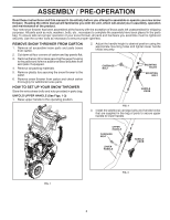
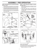
ASSEMBLY / PRE-OPERATION INSTALL DISCHARGE CHUTE / CHUTE ROTATOR HEAD (See Fig. 4 and 5) 1. Place discharge chute assembly on top of chute base with discharge opening toward front of snow thrower. 2. Position chute rotator head over chute bracket. If necessary, rotate chute assembly to align square - Poulan PR270A | Owners Manual - Page 7
meaning. DANGER OR WARNING EAR PROTECTION RECOMMENDED READ AND FOLLOW ALL SAFETY INFORMATION AND INSTRUCTIONS BEFORE USE OF THIS PRODUCT. KEEP THESE INSTRUCTIONS FOR FUTURE REFERENCE. DANGER READ OPERATORS MANUAL DO NOT OPERATE ON STEEP SLOPES WATCH FOR THROWN OBJECTS OPERATE AT A SAFE DISTANCE - Poulan PR270A | Owners Manual - Page 8
fuel flow to the engine. Traction drive control lever - used to engage powerpropelled forward or reverse motion of snow thrower. Auger control lever - used to engage auger motion (throw snow). Discharge chute control lever - used to change the direction the snow is thrown. Deflector remote control - Poulan PR270A | Owners Manual - Page 9
startup. WARNING: If the discharge chute or auger become clogged, shut-off engine and wait for all moving parts to stop. Use the clean-out tool, Be sure lever springs back and locks into desired position. OFF FUELCONTROL INSTRUCTIONS DISCHARGE CHUTE CONTROL LEVER ON FIG. 9 TO USE CHOKE CONTROL ( - Poulan PR270A | Owners Manual - Page 10
clean-out tool to dislodge this blockage. When cleaning, repairing, or inspecting, make certain all controls are disengaged and the auger/impeller and all moving parts have stopped. Disconnect the spark plug wire and keep the wire away from the spark plug to prevent accidental starting. • Release - Poulan PR270A | Owners Manual - Page 11
parts bag may be used to adjust the skid plates. Skid plates are located on each side of the auger thrown by the impeller, which can providing additional service before requiring Maintenance section of this manual. ADD GASOLINE (See Fig. avoid engine problems, the fuel Storage Instructions for - Poulan PR270A | Owners Manual - Page 12
downwind whenever possible. • Adjust the skid plates to proper height for current snow conditions. See "TO ADJUST SKID PLATES" in this section of this manual. • For extremely heavy snow, reduce the width of snow removal by overlapping previous path and moving slowly. • Keep engine clean and clear of - Poulan PR270A | Owners Manual - Page 13
a year, you should replace the spark plug and check belts for wear. A new spark plug will help your engine run better and last longer. • Follow the maintenance schedule in this manual. NOTE: Use only Original Equipment Manufacturer (OEM) parts to service this unit. Failure to do so can cause the - Poulan PR270A | Owners Manual - Page 14
from your local parts dealer. Tire sealant also prevents tire dry rot and corrosion. BELTS Check belts for deterioration and belts are not adjustable. Replace belts if they begin to slip from wear. (See "TO REMOVE BELT COVER" in the Service and Adjustments section of this manual). The belts - Poulan PR270A | Owners Manual - Page 15
1/4-20 LOCKNUT 1/4-20 x 2 SHOULDER / SHEAR BOLT IMPELLER HUB IMPELLER SHAFT AUGER HUB 1/4-20 LOCKNUT AUGER HUB AUGER SHAFT FIG. 17 TO REMOVE BELT COVER (See Fig. 18) 1. Loosen the two (2) screws securing belt cover to frame. 2. Remove belt cover. • Replace belt cover by installing cover and - Poulan PR270A | Owners Manual - Page 16
components are moving correctly. Continue with "AFTER REPLACING BELTS" instructions. ENGINE PULLEY AUGER BELT TENSIONER ARM AUGER BELT HANDLE MOUNTING BRACKET FIG. 19 3. REMOVE BELT COVER - See "TO REMOVE BELT COVER" in this section of this manual. 16 FRAME UPPER ASSEMBLY 5/16" BOLT LOWER - Poulan PR270A | Owners Manual - Page 17
SERVICE AND ADJUSTMENTS DRIVE BELT REPLACEMENT (See Fig. 21) TO REMOVE DRIVE BELT 1. Remove auger belt. See "TO REMOVE AUGER BELT" in this section. 2. Remove tensioner spring attached to drive belt tensioner arm. 3. Remove return spring holding the swing plate in place. 4. Remove arm bolt and drive - Poulan PR270A | Owners Manual - Page 18
manual). 2. Inspect and replace belts, if necessary (See "TO REPLACE BELTS" in the Service and Adjustments section of this manual). 3. Lubricate as shown in the Maintenance section of this manual. 4. Be sure that all nuts, bolts, screws, and pins are securely fastened. Inspect moving parts problems. - Poulan PR270A | Owners Manual - Page 19
parts or damaged augers or 1. Tighten all fasteners. Replace damaged parts. If vibration impeller. remains, contact an authorized service center/department. Recoil starter is 1. Frozen recoil starter. hard to pull 1. See "IF RECOIL STARTER HAS FROZEN" in the Operation section of this manual - Poulan PR270A | Owners Manual - Page 20
REPAIR PARTS SNOW THROWER - MODEL PR270A (96192009601) AUGER HOUSING / IMPELLER ASSEMBLY 3 14 14 15 14 10 14 11 13 13 12 13 9 8 6 9 4 8 5 13 2 1 7 7 6 7 05.09.009-J 6 NOTE: All component dimensions given in U.S. inches. 1 inch = 25.4 - Poulan PR270A | Owners Manual - Page 21
PARTS SNOW THROWER - MODEL PR270A (96192009601) AUGER HOUSING / IMPELLER ASSEMBLY KEY NO. 1 2 3 4 5 6 7 8 9 10 11 12 13 14 15 PART AUGER BELT GUIDE NOTE: All component dimensions given in U.S. inches. 1 inch = 25.4 mm IMPORTANT: Use only Original Equipment Manufacturer (O.E.M.) replacement parts - Poulan PR270A | Owners Manual - Page 22
PARTS SNOW THROWER - MODEL PR270A (96192009601) AUGER HOUSING / IMPELLER ASSEMBLY 1 3 5X 2 4 5X KEY NO. 1 2 3 4 PART NO. 581 70 83-73 532 41 53-71 872 27 05-05 532 15 53-77 DESCRIPTION AUGER HOUSING SCRAPER BAR CARRIAGE BOLT 5/16-18 X .625 GR5 NUT 5/16-18 05.09.011-C 2 1 KEY NO. 1 2 PART - Poulan PR270A | Owners Manual - Page 23
SNOW THROWER - MODEL PR270A (96192009601) AUGER HOUSING / IMPELLER ASSEMBLY 1 05.09.039-A 2 3 KEY NO. 1 2 3 PART NO. 532 19 21-99 532 40 54-00 532 19 41-89 DESCRIPTION TOOL CLEANOUT CLIP CLEANOUT TOOL SCREW HEX WASHER 13-16 X 5/8 1 2 3 3 05.09.007-A 1 2 3 KEY PART NO. NO. DESCRIPTION - Poulan PR270A | Owners Manual - Page 24
SNOW THROWER - MODEL PR270A (96192009601) AUGER HOUSING / IMPELLER ASSEMBLY 2 KEY PART NO. NO. DESCRIPTION 1 532 43 59 inch = 25.4 mm IMPORTANT: Use only Original Equipment Manufacturer (O.E.M.) replacement parts. Failure to do so could be hazardous, damage your snow thrower and void your warranty - Poulan PR270A | Owners Manual - Page 25
PARTS SNOW THROWER - MODEL PR270A (96192009601) CONTROL PANEL / DISCHARGE CHUTE 1 5 5 05.08.010-A 2 5 4 7 43 4 6 KEY NO. 1 2 3 4 5 6 7 PART 25.4 mm IMPORTANT: Use only Original Equipment Manufacturer (O.E.M.) replacement parts. Failure to do so could be hazardous, damage your snow thrower - Poulan PR270A | Owners Manual - Page 26
PR270A (96192009601) CONTROL PANEL / DISCHARGE CHUTE 6 8 1 37 4 2 4 5 05.08.011-B KEY NO. 1 2 3 4 5 6 7 8 PART NO. 588 11 37-02 588 11 38-01 588 12 23-01 532 19 79-91 532 42 81-24 581 32 94-01 532 42 33-03 585 80 83-01 DESCRIPTION CABLE CONTROL DRIVE CABLE CONTROL AUGER - Poulan PR270A | Owners Manual - Page 27
SNOW THROWER - MODEL PR270A (96192009601) CONTROL PANEL / DISCHARGE CHUTE KEY PART NO. NO. DESCRIPTION 3 3 2 1 587 33 25-02 25.4 mm IMPORTANT: Use only Original Equipment Manufacturer (O.E.M.) replacement parts. Failure to do so could be hazardous, damage your snow thrower and void your - Poulan PR270A | Owners Manual - Page 28
- MODEL PR270A (96192009601) CONTROL PANEL / DISCHARGE CHUTE 1 3 2 05.07.021-A 2 KEY NO. 1 2 3 PART NO. 581 13 12-06 817 06 04-10 581 32 95-01 DESCRIPTION CONSOLE BASE MULTI CONTROL SCREW TA SEMI GIMLE 1/4-20 X .62 SCREW HEX WASHER 13-16 X 1.50 2 3 2 3 1 05.07.007-A KEY NO. 1 2 3 PART NO - Poulan PR270A | Owners Manual - Page 29
PARTS SNOW THROWER - MODEL PR270A (96192009601) CONTROL PANEL / DISCHARGE CHUTE 84 9 7 3 3 10 6 10 1 58 9 6 2 7 05.08.012-A KEY NO. 1 2 3 4 5 6 7 8 9 10 PART ROT BOLT SHOULDER 1/4-20 SPRING COMPRESSION NUT FL LOCK 1/4-20 BRACE SUPPORT SPEED WASHER .625 X .375 X .094 NYLON 6/6 NOTE: All - Poulan PR270A | Owners Manual - Page 30
REPAIR PARTS SNOW THROWER - MODEL PR270A (96192009601) CONTROL PANEL / DISCHARGE CHUTE 8 10 9 10 7 *11 *16 *13 *12 2 7 3 4 4 *15 1 *14 4 4 6 4 5 05.11.006-E KEY NO. 1 2 3 4 5 6 7 8 9 10 *11 *12 *13 *14 *15 *16 PART NO. 588 07 78-02 586 96 15-01 581 32 94-01 585 80 83-01 532 42 33 - Poulan PR270A | Owners Manual - Page 31
HEAD WITH PATCH 3 05.06.001-G 1 2 4 3 2 4 05.05.001-E KEY NO. 1 2 3 4 PART NO. 588 67 21-02 817 00 06-12 581 62 20-02 817 00 05-10 DESCRIPTION LOWER HANDLE SCREW HEX WASH HD 3/8-16 X .75 CHUTE ROTATOR SUPPORT ASM BOLT HEX 5/16-18 NOTE: All component dimensions given in - Poulan PR270A | Owners Manual - Page 32
SNOW THROWER - MODEL PR270A (96192009601) 3 4 12 6 5 2 6 10 11 9 7 8 12 13 14 15 16 18 13 12 19 17 13 20 05.02.001-G NOTE: All component dimensions given in U.S. inches. 1 inch = 25.4 mm IMPORTANT: Use only Original Equipment Manufacturer (O.E.M.) replacement parts. Failure to do - Poulan PR270A | Owners Manual - Page 33
SNOW THROWER - MODEL PR270A (96192009601) KEY NO. 1 2 3 4 5 6 7 8 9 10 11 12 13 14 15 16 17 18 19 20 PART NO. 585 69 15-01 inch = 25.4 mm IMPORTANT: Use only Original Equipment Manufacturer (O.E.M.) replacement parts. Failure to do so could be hazardous, damage your snow thrower and void your - Poulan PR270A | Owners Manual - Page 34
SNOW THROWER - MODEL PR270A (96192009601) 6 1 2 6 4 3 2 1 05.03.001-B 8 7 3 5 5 3 KEY NO. 1 2 3 4 5 6 7 8 PART NO. 532 44 1 inch = 25.4 mm IMPORTANT: Use only Original Equipment Manufacturer (O.E.M.) replacement parts. Failure to do so could be hazardous, damage your snow thrower and void - Poulan PR270A | Owners Manual - Page 35
PARTS SNOW THROWER - MODEL PR270A (96192009601) CHASSIS / ENGINE / PULLEYS 5 5 7 8 55 3 54 7 6 6 6 65 05.01.006-C 2 2 22 86 6 5 6 1 6 5 KEY NO. - - 1 2 3 4 5 6 7 8 PART CLIP WASHER .343 X .750 X 16GA BLACK KEY NO. 1 PART NO. DESCRIPTION 583 94 05-02 SMALL MOUNTING PLATE 1 05.01. - Poulan PR270A | Owners Manual - Page 36
SNOW THROWER - MODEL PR270A (96192009601) CHASSIS / ENGINE / PULLEYS 3 2 2 1 4 4 05.04.002-B KEY NO. 1 2 3 4 PART NO. 587 10 54-01 532 14 50-06 DESCRIPTION BELT COVER BLACK ASSEMBLY (INCLUDES 2 & 4) BOLT HEX WSH THDRL 1/4-20 X 1 CABLE GUIDE PALNUT 1/4 IN NOTE: All component dimensions - Poulan PR270A | Owners Manual - Page 37
4L X 38.2 IMPELLER BELT IDLER PULLEY 2.0 FLANGELESS W/SPACER NOTE: All component dimensions given in U.S. inches. 1 inch = 25.4 mm IMPORTANT: Use only Original Equipment Manufacturer (O.E.M.) replacement parts. Failure to do so could be hazardous, damage your snow thrower and void your warranty - Poulan PR270A | Owners Manual - Page 38
WHEELS SNOW THROWER - MODEL PR270A (96192009601) 1 KEY PART NO. NO. DESCRIPTION 2 1 586 71 04-02 WHEEL 15 X inch = 25.4 mm IMPORTANT: Use only Original Equipment Manufacturer (O.E.M.) replacement parts. Failure to do so could be hazardous, damage your snow thrower and void your warranty. 38 - Poulan PR270A | Owners Manual - Page 39
PARTS BAG OF PARTS SNOW THROWER - MODEL PR270A (96192009601) 8 7 11 3 12 4 9 5 6 1 2 10 05.18.008-B KEY NO. 1 2 3 4 5 6 7 8 9 10 11 12 NI PART KNOB SOFT TOUCH SLOTTED WASHER NYLON KIT REPLACEMETN BAG OF PARTS 1 01.14.009-B KEY NO. 1 PART NO. DESCRIPTION 532 44 30-59 SAFETY IGNITION KEY KIT - Poulan PR270A | Owners Manual - Page 40
DECALS SNOW THROWER - MODEL PR270A (96192009601) KEY PART NO. NO. DESCRIPTION 1 1 532 18 40-45 DECAL AUGER 4 2 532 19 96-82 DECAL CHUTE 3 532 19 96-83 DECAL AUGER SAFETY 4 532 18 40-28 DECAL BELT GUIDE 3 2 05.16.001-A NOTE: All component dimensions given in U.S. inches. 1 inch = 25 - Poulan PR270A | Owners Manual - Page 41
SNOW THROWER - MODEL PR270A (96192009601) 7 8 3 7 8 KEY NO. 3 4 7 8 - - - - PART NO. 532 19 96-82 532 18 40-45 532 18 40-28 532 19 96-83 115 82 01-27 115 82 01-31 115 82 01-46 DESCRIPTION DECAL, DANGER, DEFLECTOR DECAL, DANGER DECAL DECAL OWNER'S MANUAL, ENGLISH OWNER'S MANUAL, FRENCH OWNER - Poulan PR270A | Owners Manual - Page 42
SNOW THROWER - MODEL PR270A (96192009601) COMPLETE ENGINE - 580426005 KEY PART NO. NO. DESCRIPTION KEY PART NO. NO. DESCRIPTION 1 532 42 05-78 CYLINDER HEAD ASSEMBLY - 16 532 42 49-42 FUEL TANK CAP - BLACK CLLCK 208CC (INCL. GASKET) STYLE (VENTED) - Poulan PR270A | Owners Manual - Page 43
SNOW THROWER - MODEL PR270A (96192009601) COMPLETE ENGINE - 580426005 KEY PART NO. NO. DESCRIPTION 29 532 42 49-66 KEY SET - RED (2) (SNOW) 55 532 43 26-86 OIL DRAIN TUBE-SNOW (136/208CC) KEY PART NO. NO. DESCRIPTION 56 585 77 33-01 CARBURETOR VAPOR SHIELD 57 N/A N/A 58 532 42 49-60 - Poulan PR270A | Owners Manual - Page 44
05.18.16 TH Printed in the U.S.A.
-
 1
1 -
 2
2 -
 3
3 -
 4
4 -
 5
5 -
 6
6 -
 7
7 -
8
-
9
-
10
-
11
-
12
-
13
-
14
-
15
-
16
-
17
-
18
-
19
-
20
-
21
-
22
-
23
-
24
-
25
-
26
-
27
-
28
-
29
-
30
-
31
-
32
-
33
-
34
-
35
-
36
-
37
-
38
-
39
-
40
-
41
-
42
-
43
-
44
 |
 |
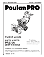
OWNER'S MANUAL
MODEL NUMBER:
PR270A
SNOW THROWER
Always Wear Eye Protection During Operation
IMPORTANT MANUAL
Do Not Throw Away
WARNING:
Read the Owner's Manual and
follow all Warnings and Safety
Instructions.
Failure to do so
can result in serious injury.
115 82 01-27 Rev. 1
Gasoline containing up to 10% ethanol (E10) is acceptable for use in this machine.
The use of any gasoline exceeding 10% ethanol (E10) will void the product warranty.