Poulan PR624 User Manual
Poulan PR624 Manual
 |
View all Poulan PR624 manuals
Add to My Manuals
Save this manual to your list of manuals |
Poulan PR624 manual content summary:
- Poulan PR624 | User Manual - Page 1
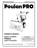
IMPORTANT MANUAL Do Not Throw Away OWNER'S MANUAL MODEL NUMBER: PR624 SNOW THROWER WARNING: Read the Owner's Manual and follow all Warnings and Safety Instructions. Failure to do so can result in serious injury. Always Wear Eye Protection During Operation 436132 Rev 1 05.20.10 JA/TH Printed in - Poulan PR624 | User Manual - Page 2
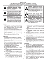
instructions could result in serious injury. Look for this symbol to point out important safety precautions. It means CAUTION!!! BECOME ALERT!!! YOUR SAFETY IS INVOLVED. WARNING: Always disconnect spark plug instructions on the machine and in the manual generally a warning of trouble. from the truck - Poulan PR624 | User Manual - Page 3
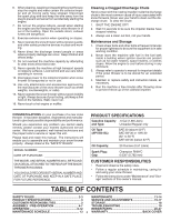
Liters) Spark Plug: Gap: Champion RN9YC 0.030" (0,762 mm) CUSTOMER RESPONSIBILITIES • Read and observe the safety rules. • Follow a regular schedule in maintaining, caring for and using your snow thrower. • Follow the instructions under "Maintenance" and "Storage" sections of this owner's manual - Poulan PR624 | User Manual - Page 4
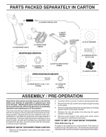
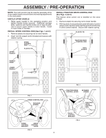
) EXTRA SHEAR BOLTS AND NUTS (2) HANDLE KNOBS (2) SHEAR BOLTS 1/4-20 x 1-3/4 (192090) (2) LOCKNUTS 1/4-20 (73800400) ASSEMBLY / PRE-OPERATION Read these instructions and this manual in its entirety 2. Cut down all four corners of carton and lay panels flat. before you attempt to assemble or - Poulan PR624 | User Manual - Page 5
ASSEMBLY / PRE-OPERATION NOTE: The multi-wrench may be used for assembly of the chute rotator head to snow thrower and making adjustments to the skid plates. UNFOLD UPPER HANDLE 1. Raise upper handle to the operating position and tighten handle knobs securely. Additional carriage bolts, washers and - Poulan PR624 | User Manual - Page 6
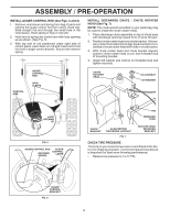
ASSEMBLY / PRE-OPERATION INSTALL AUGER CONTROL ROD (See Figs. 5 and 6) 1. Retrieve vinyl sleeve and spring from bag of parts and retrieve the auger control rod from carton chute tray. Slide straight rod end through the small hole in the vinyl sleeve. Hook spring in hole in rod end. 2. Hook end of - Poulan PR624 | User Manual - Page 7
yourself with the location of various controls and adjustments. Save this manual for future reference. These symbols may appear on your snow READ AND FOLLOW ALL SAFETY INFORMATION AND INSTRUCTIONS BEFORE USE OF THIS PRODUCT. KEEP THESE INSTRUCTIONS FOR FUTURE REFERENCE. IGNITION KEY. INSERT - Poulan PR624 | User Manual - Page 8
MUFFLER GASOLINE FILLER CAP CHOKE CONTROL SAFETY IGNITION KEY ON / OFF SWITCH PRIMER FUEL SHUT-OFF VALVE RECOIL STARTER HANDLE OPERATION AUGER CONTROL LEVER DISCHARGE CHUTE CONTROL LEVER DRIVE SPEED CONTROL LEVER TRACTION DRIVE CONTROL LEVER CHUTE DEFLECTOR DISCHARGE CHUTE CLEAN-OUT TOOL - Poulan PR624 | User Manual - Page 9
OPERATION The operation of any snow thrower can result in foreign objects thrown into the eyes, which can result in severe eye damage. Always wear safety glasses or eye shields while operating your snow thrower or performing any adjustments or repairs. We recommend standard safety glasses or a wide - Poulan PR624 | User Manual - Page 10
inspecting, make certain all controls are disengaged and the auger/impeller and all moving parts have stopped. Disconnect the spark plug wire and keep the wire away from the spark plug to prevent accidental starting. • Release the auger control lever and shut off the engine. • Remove the clean-out - Poulan PR624 | User Manual - Page 11
storage. To avoid engine problems, the fuel system should next season. See Storage Instructions for additional information. Never can be reversed, providing additional service before requiring replacement. Replace ENGINE OIL" in the Maintenance section of this manual. ADD GASOLINE (See Fig. 17) • - Poulan PR624 | User Manual - Page 12
downwind whenever possible. • Adjust the skid plates to proper height for current snow conditions. See "TO ADJUST SKID PLATES" in this section of this manual. • For extremely heavy snow, reduce the width of snow removal by overlapping previous path and moving slowly. • Keep engine clean and clear of - Poulan PR624 | User Manual - Page 13
from the warranty, operator must maintain snow thrower as instructed in this manual. Some adjustments will need to be made periodically to properly Service and Adjustments section of this manual. • At least once a year, you should replace the spark plug and check belts for wear. A new spark plug - Poulan PR624 | User Manual - Page 14
. (See "TO REMOVE WHEELS" in the Service and Adjustments section of this manual). 1. Remove safety ignition key and disconnect spark plug wire from spark plug and place wire where it cannot come in contact with plug. 2. Clean area around drain plug. 3. Remove drain plug and drain oil in a suitable - Poulan PR624 | User Manual - Page 15
service or adjustments: 1. Be sure the on/off switch is in the OFF position. 2. Remove safety ignition key. 3. Make sure the augers and all moving parts have completely stopped. 4. Disconnect spark plug wire from spark plug DISCHARGE" in the Operation section of this manual. SHEAR BOLTS (See Fig. 18) - Poulan PR624 | User Manual - Page 16
should be replaced. It is recommended that the belt(s) be replaced by a service center/department. NOTE: It is recommended that both the auger and traction drive COVER - See "TO REMOVE BELT COVER" in this section of this manual. 4. REMOVE ENGINE PULLEY - Remove bolt, flat washer securing pulley to - Poulan PR624 | User Manual - Page 17
sealant also prevents tire dry rot and corrosion. ENGINE See engine manual. CARBURETOR Your carburetor is not adjustable. Engine performance should not not operate properly due to suspected carburetor problems, take your snow thrower to a qualified service center. ENGINE SPEED Never tamper with the - Poulan PR624 | User Manual - Page 18
REPLACE BELTS" in the Service and Adjustments section of this manual). 3. Lubricate as shown in the Maintenance section of this manual. 4. Be sure the Maintenance section of this manual). CYLINDER 1. Remove spark plug. 2. Pour one ounce (29 ml) of oil through spark plug hole into cylinder. 3. Pull - Poulan PR624 | User Manual - Page 19
TROUBLESHOOTING See appropriate section in manual unless directed to an authorized service center/department. PROBLEM CAUSE CORRECTION instructed in the Operation section of this manual. 7. Wait a few minutes before restarting, DO NOT prime. 8. Connect wire to spark plug. 9. Replace spark plug - Poulan PR624 | User Manual - Page 20
REPAIR PARTS SNOW THROWER - - MODEL NUMBER PR624 (96192004200) AUGER HOUSING / IMPELLER ASSEMBLY 5 15 14 4 11 6 11 16 12 13 11 3 12 10 11 7 8 17 1 9 37 2 9 9 33 37 32 34 30 31 31 - Poulan PR624 | User Manual - Page 21
REPAIR PARTS SNOW THROWER - - MODEL NUMBER PR624 (96192004200) AUGER HOUSING / IMPELLER ASSEMBLY KEY NO. 1 2 3 4 5 X .625 IMPELLER HUB IMPELLER SLEEVE NUT 3/8-16 CARRIAGE BOLT SCREW 13-16 X .625 PLUG GEARBOX COVER RH GASKET SEAL BEARING THRUST WASHER 1.00 WORM GEAR AUGER SHAFT SQUARE KEY BEARING - Poulan PR624 | User Manual - Page 22
REPAIR PARTS SNOW THROWER - - MODEL NUMBER PR624 (96192004200) AUGER HOUSING / IMPELLER ASSEMBLY 1 KEY NO. 1 2 3 4 PART NO. 404928X421 404931X431 72270505 155377 DESCRIPTION AUGER HOUSING SCRAPPER BAR CARRIAGE BOLT 5/16−18 X .625 NUT 5/16− - Poulan PR624 | User Manual - Page 23
REPAIR PARTS SNOW THROWER - - MODEL NUMBER PR624 (96192004200) AUGER HOUSING / IMPELLER ASSEMBLY 2 3 1 1 2 3 01.07.024-B KEY NO. 1 2 3 PART NO. 420478 411939 179582 DESCRIPTION AUGER BEARING BEARING PLUG SCREW 5/16−18 X 1.00 4 3 2 3 KEY PART NO. NO. DESCRIPTION 1 174762X431 SKID PLATE - Poulan PR624 | User Manual - Page 24
REPAIR PARTS SNOW THROWER - - MODEL NUMBER PR624 (96192004200) CONTROL PANEL / CHUTE 2 3 6 1 11 10 5 8 6 9 11 4 11 7 6 13 12 01.09.005-E KEY NO. 1 2 3 4 5 6 7 8 9 10 11 12 13 PART NO. 435023X421 178633X421 420325 179096X421 - Poulan PR624 | User Manual - Page 25
REPAIR PARTS SNOW THROWER - - MODEL NUMBER PR624 (96192004200) CONTROL PANEL / CHUTE 2 2 *3 1 *7 *6 KEY NO. 1 2 *3 *4 *5 *6 *7 PART NO. 010-B *5 NOTES: 1. ITEMS INDICATED WITH AN * ARE LISTED AS REFERENCE FOR SERVICE PARTS ONLY. NOTE: All component dimensions given in U.S. inches. 1 inch = 25 - Poulan PR624 | User Manual - Page 26
REPAIR PARTS SNOW THROWER - - MODEL NUMBER PR624 (96192004200) HANDLES 5 1 6 8 5 8 6 2 39 7 8 49 7 KEY NO. 01.08.003-A 1 KEY PART NO. NO. DESCRIPTION 1 419797X431 LOWER HANDLE 2 427513X431 PIVOT SUPPORT WELDMENT 3 428867 SCREW 5/16−18 X .750 2 4 17000616 SCREW 3/8−16 X 1.00 4 - Poulan PR624 | User Manual - Page 27
REPAIR PARTS SNOW THROWER - - MODEL NUMBER PR624 (96192004200) HANDLES 10 2 11 9 5 7 6 8 47 9 1 3 8 12 13 13 14 01.08.002-F 14 12 KEY NO. 1 2 3 4 5 6 7 8 9 10 11 12 13 14 PART NO. 412683X431 424517X431 - Poulan PR624 | User Manual - Page 28
REPAIR PARTS SNOW THROWER - - MODEL NUMBER PR624 (96192004200) HANDLES 10 1 2 10 3 8 9 4 KEY NO. 1 2 3 4 5 6 7 8 9 10 PART NO. 180480 405740 180445 187716 180447 178669 180926 72270505 155377 169675 DESCRIPTION IMPELLER ROD TRACTION ROD SHIFTER - Poulan PR624 | User Manual - Page 29
REPAIR PARTS SNOW THROWER - - MODEL NUMBER PR624 (96192004200) HANDLES 1 2 3 3 01.10.001-B 2 KEY NO. 1 2 3 PART NO. 183352 184471 175262 DESCRIPTION CONSOLE PANEL SCREW 10−24 X .625 SCREW 10−24 X 1.25 4 5 2 1 6 KEY NO. 1 2 3 4 5 - Poulan PR624 | User Manual - Page 30
REPAIR PARTS SNOW THROWER - - MODEL NUMBER PR624 (96192004200) DRIVE 42 EXPLODED 2 16 1 17 15 14 15 12 9 11 11 20 9 9 10 11 53 13 53 19 8 7 53 21 6 5 45 18 22 34 - Poulan PR624 | User Manual - Page 31
REPAIR PARTS SNOW THROWER - - MODEL NUMBER PR624 (96192004200) DRIVE KEY NO. 1 2 3 4 5 6 7 8 9 10 11 12 13 14 15 16 17 18 19 20 21 22 23 24 25 26 PART NO. 198875 17501010 - Poulan PR624 | User Manual - Page 32
REPAIR PARTS SNOW THROWER - - MODEL NUMBER PR624 (96192004200) DRIVE 5 6 1b 7 4 3 1b 6 1a KEY PART NO. NO. DESCRIPTION 2 1 188226 (assy of 1a,1b) AXLE ASSEMBLY 3 1a 179352 AXLE SHAFT 1b 9465M ROLL PIN 3/ - Poulan PR624 | User Manual - Page 33
REPAIR PARTS SNOW THROWER - - MODEL NUMBER PR624 (96192004200) CHASSIS / ENGINE / PULLEYS 2 3 2 3 1 1 01.00.034-A KEY NO. - 1 2 3 PART NO. 421575 418694X421 150406 428867 DESCRIPTION COMPLETE LCT ENGINE FRAME BOLT 3/8-16 SCREW 5/16-18 X . - Poulan PR624 | User Manual - Page 34
REPAIR PARTS SNOW THROWER - - MODEL NUMBER PR624 (96192004200) CHASSIS / ENGINE / PULLEYS 23 22 24 14 21 20 11 PULLEY ENG IMPELLER PULLEY ENG TRACTION SCREW 5/16-18 X 1 .00 LOCKWASHER 5/16 BELT GUIDE LOCKWASHER 5/16 IDLER BUSHING NOTE: All component dimensions given in U.S. inches. 1 inch = - Poulan PR624 | User Manual - Page 35
REPAIR PARTS SNOW THROWER - - MODEL NUMBER PR624 (96192004200) WHEELS 1 KEY NO. 1 2 PART NO. 432331X428 432332X428 DESCRIPTION WHEEL ASSEMBLY LH WHEEL ASSEMBLY RH 2 01.06.018-A NOTE: All component dimensions given in U.S. inches. 1 - Poulan PR624 | User Manual - Page 36
REPAIR PARTS SNOW THROWER - - MODEL NUMBER PR624 (96192004200) BAG OF PARTS 3 2 1 01.14.004-B 45 7 6 KEY NO. 1 2 3 4 5 6 7 PART NO. 198563 169675 180684X008 73800600 19131316 192090 73800400 DESCRIPTION POWER CORD RETAINER PIN WRENCH - Poulan PR624 | User Manual - Page 37
REPAIR PARTS SNOW THROWER - - MODEL NUMBER PR624 (96192004200) DECALS 1 4 9 6 1 3 KEY NO. 1 3 4 6 7 9 - - - PART NO. 181037 181035 181042 181033 428716 429591 436132 436133 DESCRIPTION DECAL, DANGER DECAL, DANGER, DEFLECTOR DECAL, DANGER DECAL, INSTRUCTION DECAL, CONS. LT WO/LEV/PWRST - Poulan PR624 | User Manual - Page 38
SERVICE NOTES 38 - Poulan PR624 | User Manual - Page 39
SERVICE NOTES 39 - Poulan PR624 | User Manual - Page 40
must be maintained in accordance with the instructions furnished. 4. The Warranty period for any Poulan Pro Outdoor Products Customer Service Dept. 9335 Harris Corners Parkway Charlotte, NC 28269 USA In Canada contact: Poulan Pro 5855 Terry Fox Way Mississauga, Ontario L5V 3E4 giving the model
-
 1
1 -
 2
2 -
 3
3 -
 4
4 -
 5
5 -
 6
6 -
 7
7 -
8
-
9
-
10
-
11
-
12
-
13
-
14
-
15
-
16
-
17
-
18
-
19
-
20
-
21
-
22
-
23
-
24
-
25
-
26
-
27
-
28
-
29
-
30
-
31
-
32
-
33
-
34
-
35
-
36
-
37
-
38
-
39
-
40
 |
 |

OWNER'S MANUAL
MODEL NUMBER:
PR624
SNOW THROWER
Always Wear Eye Protection During Operation
IMPORTANT MANUAL
Do Not Throw Away
WARNING:
Read the Owner's Manual and
follow all Warnings and Safety
Instructions.
Failure to do so
can result in serious injury.
436132 Rev 1
05.20.10
JA/TH
Printed in the U.S.A.