ProForm 2 English Manual
ProForm 2 Manual
 |
View all ProForm 2 manuals
Add to My Manuals
Save this manual to your list of manuals |
ProForm 2 manual content summary:
- ProForm 2 | English Manual - Page 1
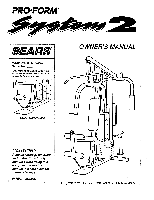
below. Write the serial number in the space above. c 0 Serial Number Decal OWNER'S MANUAL 0 CAUTION!: Read all safety precautions and instructions in this manual before using this equipment. Keep this manual in a safe place for future reference. PATENT PENDING da? SEARS, ROEBUCK AND CO., HOFFMAN - ProForm 2 | English Manual - Page 2
OF CONTENTS IMPORTANT SAFETY PRECAUTIONS BEFORE YOU BEGIN ASSEMBLY USING THE SYSTEM 2 TROUBLE-SHOOTING AND MAINTENANCE PART LIST EXPLODED DRAWING ORDERING REPLACEMENT PARTS LIMITED WARRANTY 2 3 4 12 13 14 15 Back Cover Back Cover IMPORTANT SAFETY PRECAUTIONS WARNING: To reduce the risk of serious - ProForm 2 | English Manual - Page 3
manual carefully before using the PROFORM SYSTEM 2. If you have additional questions, please call our Customer Service Department on a decal attached to the PROFORM SYSTEM 2 (see the front cover of this manual). Before reading further, please Weight Selector Small Seat Small Weight Weight Pin Large - ProForm 2 | English Manual - Page 4
ASSEMBLY Due to the size and weight of the SYSTEM 2, assemble the SYSTEM 2 in the location where it will be used. in the drawings. Refer to the Part Identification (I.D.) Chart accompanying this owner's manual for help identifying the small parts used in assembly. The following tools are required - ProForm 2 | English Manual - Page 5
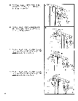
extension tube on it.) Insert the post through the left end of the Butterfly Arm Support (49). Tap a 1/2" Plastic Cap (63) onto the post. Wet the lower the lower end. Attach the Right Butterfly Arm (46) to the Butterfly Arm Support in the same manner. 6. Lay the sixteen Pulleys (10) on the floor - ProForm 2 | English Manual - Page 6
8. Attach two Pulleys (10) to the Press Arm (27) with two 3/8" x 3 1/2" Bolts (15), 3/8" Washers (61) and 3/8" Nylock Nuts (1). 9. Attach a Pulley (10) to the Left Butterfly Arm (45) with the 3/8" x 3" Bolt (64), a 3/8" Washer (61) and a 3/8" Nylock Nut (1). 8 ti Ii c 1 ° 27 15 . 10 61 \ 9 64 - ProForm 2 | English Manual - Page 7
of the Cable.) Route one end of the Cable over the Pulley (10) attached in the previous step and over the top of the indicated Weight Guide (19). Lay the end of Cable #110290 (28) over another Pulley (10). Attach the Pulley, with a Spacer (53) on each side of it, inside the - ProForm 2 | English Manual - Page 8
3/8" x 4" Bolt (42), a 3/8" Washer (61) and a 3/8" Nylock Nut (1). Make sure that _ e the collar on the eyelet is in front of the guide pin on the Frame. 10 11 - 42 1 Tfil 61 Guide Pin 30 18. Route Cable #109461 (30) around the four Pulleys (10) attached to the Frame (11) and the praee Arm - ProForm 2 | English Manual - Page 9
. .. 6 . 10 16 11 ,,,a---15 • Guide Pin 0 29 6 1 1 10 29 21 15 29 61 1 1 . 23 10 29 , -b ,- 11 10 ') 22 46 1 29 77, 48 10 23. Attach the free end of Cable #110290 (28) inside the flattened end of the Weight Selector 23 (20) with the 3/8" x 1 1/2" Bolt (44) and a 3/8" Nylock - ProForm 2 | English Manual - Page 10
24. Press the Press Seat Rail Cap (37) into the Press Seat Rail (33). Attach the Press Seat Rail to the Large Seat (32) with two 1/4" x 3/4" Bolts (8) and 1/4" Lock Washers (7). Note: If the Leg Lever (34) is attached to the Press Seat Rail, withdraw the Leg Lever Pin (38) and set the Leg Lever - ProForm 2 | English Manual - Page 11
Large Weights are turned 20 so that the pin grooves are under the Weights and are on the same side. 57 19 56 o 56 Pin Grooves 29. Make sure that all parts are tightened securely. The use of all remaining parts is explained in USING THE SYSTEM 2, beginning on page 12 of this owner's manual - ProForm 2 | English Manual - Page 12
USING THE SYSTEM 2 The instructions below describe how the components of the SYSTEM 2 can be adjusted. See the Exercise Guide accompanying this owner's manual to see how the SYSTEM 2 should be set up for each individual exercise. ATTACHING AND REMOVING THE PRESS SEAT RAIL The press seat rail - ProForm 2 | English Manual - Page 13
TROUBLE-SHOOTING AND MAINTENANCE Inspect and tighten all parts of the SYSTEM 2 regularly. Replace any worn parts immediately. The SYSTEM slack in the weight system before resistance is Nuts, follow the instructions below. Loosen the cover of this owner's manual to order new cables. 12 16 \\ • 13 - ProForm 2 | English Manual - Page 14
18 105433 2 Weight Bumper 19 110923 2 Weight Guide 20 111182 1 Weight Selector 21 Manual # 110814 1 Exercise Manual # 104838 1 Grease Tube # 112663 1 Part I.D. Chart Note: "#" indicates a non-illustrated part. Specifications are subject to change without notice. See the back cover of this manual - ProForm 2 | English Manual - Page 15
EXPLODED DRAWING Model No. 831.159213 Rev. 3/93 61 62 52 63 49 48 46 64 47 11 53 53 2 2 53 4-61 -45 1-4 1 11 9 39-©'. 3 39 ep 42 6 61 6 47 54 7 5 50 55 \ 7 _ 7 -6( 5 28 61 11 15 10 61 15 t" 30 6-1 1 41 44 6 1 5 17 I 51 31 27 0 21 1 6 5 23 60 24 56 7 61 - ProForm 2 | English Manual - Page 16
2. The NAME of the product (PROFORM® SYSTEM 2). 3. The PART NUMBER of the part(s), from page 14 of this manual. 4. The DESCRIPTION of the part(s), from page 14 of this manual. Your Sears merchandise has added value when you consider that Sears has service units nationwide, staffed with Sears trained
-
 1
1 -
 2
2 -
 3
3 -
 4
4 -
 5
5 -
 6
6 -
 7
7 -
8
-
9
-
10
-
11
-
12
-
13
-
14
-
15
-
16
 |
 |

PRO•FORM®
65
,...
ARS
Model
No.
831.159213
Serial
No.
The
serial
number
can
be
found
in
the
location
shown
below.
Write
the
serial
number
in
the
space
above.
c
0
Serial
Number
Decal
CAUTION!:
Read
all
safety
precautions
and
instructions
in
this
manual
before
using
this
equipment.
Keep
this
manual
in
a
safe
place
for
future
reference.
PATENT
PENDING
OWNER'S
MANUAL
0
da?
SEARS,
ROEBUCK
AND
CO.,
HOFFMAN
ESTATES,
IL
60179