ProForm 500 F Elliptical English Manual - Page 6
Assembly
 |
View all ProForm 500 F Elliptical manuals
Add to My Manuals
Save this manual to your list of manuals |
Page 6 highlights
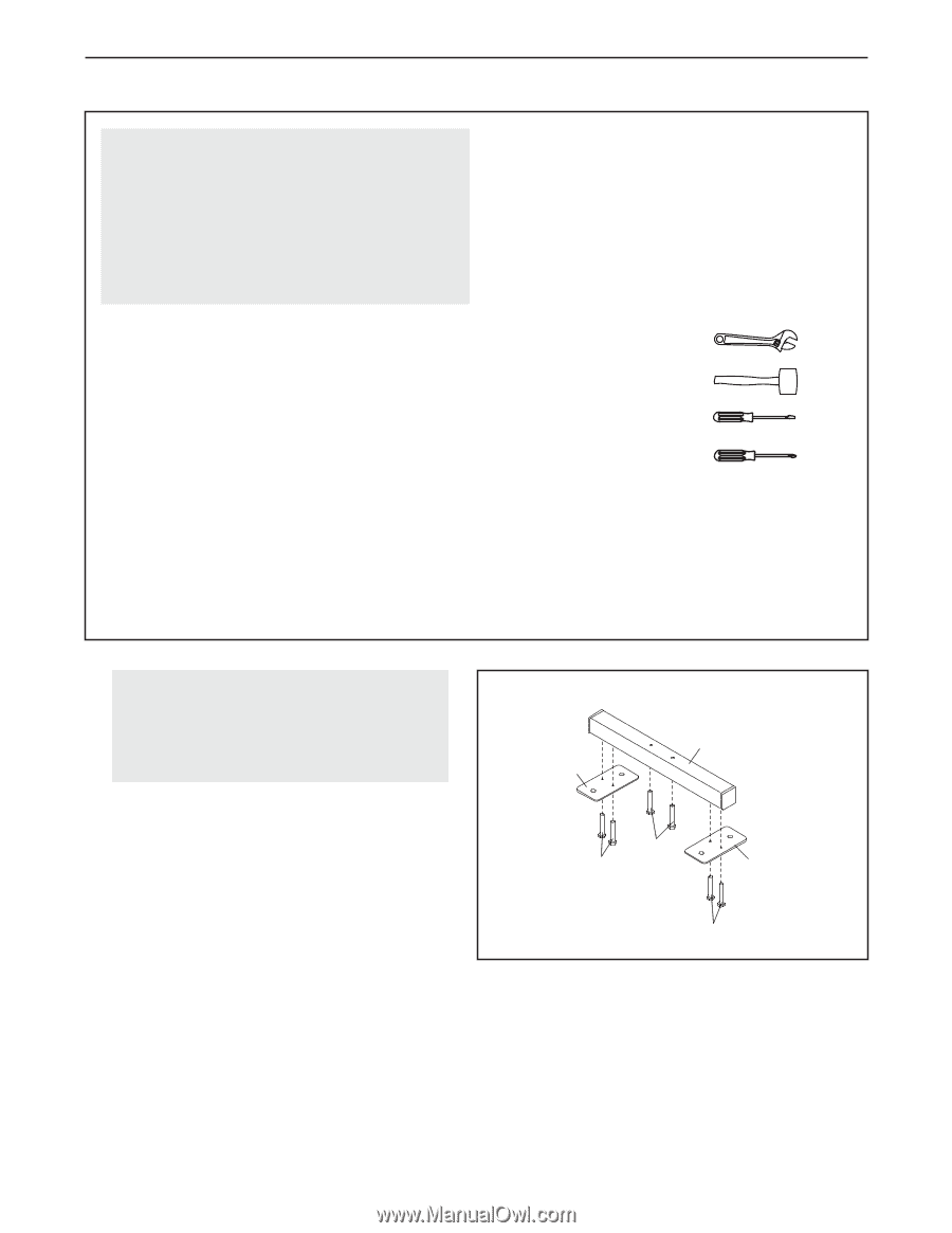
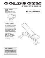
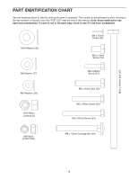
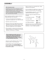
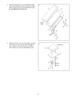
ASSEMBLY Make Assembly Easier Everything in this manual is designed to ensure that the weight bench can be assembled successfully by almost anyone. However, the weight bench has many parts and the assembly process will take time. By setting aside plenty of time, assembly will go smoothly. Before beginning assembly, carefully read the following information and instructions: • To hire an authorized service technician to assemble the weight bench, call 1-800-445-2480. • Assembly requires two persons. • Because of its size, the weight bench should be assembled in the location where it will be used. Make sure that there is enough clearance to walk around the weight bench as you assemble it. • Place all parts in a cleared area and remove the packing materials. Do not dispose of the packing materials until assembly is completed. • Tighten all parts as you assemble them, unless instructed to do otherwise. • As you assemble the weight bench, make sure all parts are oriented as shown in the drawings. • For help identifying small parts, use the PART IDENTIFICATION CHART on page 5. • Assembly requires the following tools (not included): two adjustable wrenches one rubber mallet one standard screwdriver one Phillips screwdriver Assembly may be more convenient if you have a socket set, a set of open-end or closed-end wrenches, or a set of ratchet wrenches. 1. Before beginning assembly, make sure 1 that you have read and understand the information in the box above. See the PART IDENTIFICATION CHART on page 5 for help identifying small parts. Attach the two Rear Stabilizers (5) to the Base (4) with four M4 x 15mm Screws (20). Insert two M8 x 70mm Carriage Bolts (26) up through the Base (4). It may be helpful to place a piece of tape over the Carriage Bolts to hold them in place. 4 5 26 20 5 20 6
-
 1
1 -
 2
2 -
 3
3 -
 4
4 -
 5
5 -
 6
6 -
 7
7 -
 8
8 -
 9
9 -
 10
10 -
 11
11 -
 12
12 -
13
-
14
-
15
-
16
 |
 |