ProForm 920ci English Manual
ProForm 920ci Manual
 |
View all ProForm 920ci manuals
Add to My Manuals
Save this manual to your list of manuals |
ProForm 920ci manual content summary:
- ProForm 920ci | English Manual - Page 1
of charge to you. CUSTOMER HOT LINE: 1-800-999-3756 Mon.-Fri., 6 a.m.-6 p.m. MST CAUTION Read all precautions and instructions in this manual before using this equipment. Save this manual for future reference. Visit our website at www.proform.com new products, prizes, fitness tips, and much more! - ProForm 920ci | English Manual - Page 2
feet away from moving parts. 9. Always wear athletic shoes for foot protection when exercising. 10. The weight system is intended for home use only. Do not use the weight system in a commercial, rental or institutional setting. 11. Never release the press arms, butterfly arms, leg lever, lat bar, or - ProForm 920ci | English Manual - Page 3
strength, or improve your cardiovascular system, the PROFORM® 920Ci will help you to achieve the results you want. For your benefit, read this manual carefully before using the weight system. If you have additional questions, please call our Customer Service Department toll-free at 1-800-999-3756 - ProForm 920ci | English Manual - Page 4
not dispose of the packing materials until assembly is completed. Tightening Parts Tighten all parts as you assemble them, unless instructed to do otherwise. Questions? If you have questions after reading the assembly instructions, please call our Customer Service Department toll-free at 1-800-999 - ProForm 920ci | English Manual - Page 5
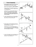
, make sure that you have read and understood the information on page 4. Open the parts bag labeled "FRAME ASSEMBLY." Press a 2" Square Inner Cap (28) into each end of the Butterfly Base (4) and into the indicated locations on the Weight Base (5). 1 28 28 4 85 92 92 5 28 28 Insert four 5/16 - ProForm 920ci | English Manual - Page 6
the bottom. Identify the Short Weight Tube (17), which has six holes in it. Press a Weight Tube Bumper (18) into the lower end of the Short Weight Tube. Slide the Weight Tube into the Weights (21). Slide a Top Weight (16) onto the Weight Guides (15). Make sure the Top Weight is turned so the groove - ProForm 920ci | English Manual - Page 7
the bottom. Identify the Long Weight Tube (96), which has twelve holes in it. Press a Weight Tube Bumper (18) into the lower end of the Long Weight Tube. Slide the Weight Tube into the Weights (21). Slide a Top Weight (16) onto the Weight Guides (15). Make sure the Top Weight is turned so the groove - ProForm 920ci | English Manual - Page 8
to the bracket on the Press Upright (2) and the Weight Top Frame (66) with four 5/16" x 2 3/4" Bolts (89), two Support Plates (94), and four 5/16" Nylon Locknuts (64). 11 64 89 66 94 2 64 9 28 94 89 28 12. Attach the Weight Guides (15) to the Weight Top Frame (66) with four 3/8" x 3 3/4" Bolts - ProForm 920ci | English Manual - Page 9
16 28 63 41 80 3 62 28 40 17. Press a 2" x 3" Inner Cap (98) into the indicated end of the Press Front Leg (20). Orient the Press Front Leg (20) with the welded rod in the position shown. Attach the Press Front Leg to the Press Base (6) with a 1/2" x 3 1/2" Bolt (105) and a 1/2" Nylon Jam Nut - ProForm 920ci | English Manual - Page 10
18. Open the parts bag labeled "ARM ASSEMBLY." Press a Plastic Bushing (100) onto each welded tube on the Press Frame (8). Lubricate the 3/8" x 9" Bolt (52). Attach the Press Frame (8) to the welded tubes on the Press Base (6) with the Bolt and a 3/8" Nylon Locknut (50). Do not overtighten the - ProForm 920ci | English Manual - Page 11
and Cable ID Chart on pages 22 and 23. Open the parts bag labeled "CABLE ASSEMBLY AND PULLEYS." Identify the Butterfly Cable (73); it is the both 3 1/2" Pulleys (24) and the Cable Traps (25) from one set of pre-assembled Pulley Plates (23). Wrap the Butterfly Cable (73) around a 3 1/2" Pulley (24) - ProForm 920ci | English Manual - Page 12
Upright. 26 63 48 47 24 74 Welded Pin 1 47 Large Tabs 48 59 27. Remove both 3 1/2" Pulleys (24) from the second set of pre-assembled Pulley Plates (23). Wrap the Ab Cable (74) around a 3 1/2" Pulley (24) in the direction shown. Attach the Pulley and a Cable Trap (25) to the top - ProForm 920ci | English Manual - Page 13
as shown. 30 63 74 24 85 25 4 31. Wrap the Ab Cable (74) around a 3 1/2" Pulley (24). Attach the Pulley to the bracket on the Weight Base (5) with a 3/8" x 1 3/4" Bolt (57) and a 3/8" Nylon Locknut (50). 31 74 24 57 5 50 Bracket 32. Wrap the Ab Cable (74) around a 4 1/2" Pulley (102) in the - ProForm 920ci | English Manual - Page 14
shown in the inset drawing. Attach the "U"-Bracket (97) to the hole in the Short Weight Tube (17) with a 5/16" x 1 3/4" Bolt (60) and a 5/16" loop on the other. Route the end with the loop through the slot in the cable guide on the Butterfly Base (4). Route the Low Cable (75) under a 3 1/2" Pulley - ProForm 920ci | English Manual - Page 15
Attach the end of the Low Cable (75) to the indicated hole in the Leg Lever (41) with a 3/8" x 2 3/4" Bolt (46), two 3/8" Flat other. Wrap the High Cable (72) over a 3 1/2" Pulley (24). Attach the Pulley to the Press Top Frame (9) with a 3/8" x 3 1/2" Bolt (56), a 3/8" Flat Washer (48), and a - ProForm 920ci | English Manual - Page 16
Wrap the High Cable (72) around a 3 1/2" Pulley (24) in the direction shown. Attach the Pulley and a Cable Trap (25) to the indicated hole in the Press Front Leg (20) with a 3/8" x 3 3/4" Bolt (59), a 3/8" Flat Washer (48), and a 3/8" Nylon Jam Nut (63). 42 72 59 24 25 20 48 63 43. Wrap the High - ProForm 920ci | English Manual - Page 17
(72) around a 3 1/2" Pulley (24) in the direction shown. Attach the Pulley and a Cable Trap (25) to the second hole in the bracket on the Press Upright (2) with a 3/8" x 2" Bolt (54) and a 3/8" Nylon Locknut (50). Make sure that the Cable Trap is oriented as shown. 47 2 Second Hole 54 24 72 - ProForm 920ci | English Manual - Page 18
Angle Spacer (103) to the 3/8" x 4" Carriage Bolt (104) in the Press Base (6). Make sure the Angle Spacer is angled exactly as shown. Secure the Pulley (102) in the direction shown. Attach the Pulley inside the indicated bracket on the Weight Top Frame (66) with a 3/8" x 2" Bolt (54) and a 3/8" - ProForm 920ci | English Manual - Page 19
. Open the parts bag labeled "SEAT ASSEMBLY." Press a 1" x 2" Inner Cap (83) into each end of a Backrest Adjustment Frame (70). Press a 1 1/4" you must remove the 2" Square Inner Cap (28) that is in the Butterfly Front Leg (3). Replace the Inner Cap when you are not using the Curl Pad. Attach the - ProForm 920ci | English Manual - Page 20
and a 1/4" Flat Washer. 58. Press 3/4" Round Inner Caps (43) into the ends of both Pad Tubes (42). Insert one Pad Tube (42) into the Leg Lever (41). Slide a Foam Pad 30 42 43 42 41 43 59. Remove the pre-assembled 1/4" x 5/8" Screws (95) from the Weight Top Frame (66). Orient one Right Shroud (34) - ProForm 920ci | English Manual - Page 21
the remaining parts will be explained in Adjustment, beginning on page 24 of this manual. Before using the weight system, pull each cable a few times to make sure that the cables move smoothly over the pulleys. If one of the cables does not move smoothly, find and correct the problem. IMPORTANT: If - ProForm 920ci | English Manual - Page 22
the pulleys move smoothly, and that the cable traps do not touch or bind the Cables. Incorrect cable routing can damage the weight system. Butterfly Cable (73) 5 4 1 2 Low Cable (75) 3 3 Ab Cable (74) 7 4 5 1 2 1 3 2 Cable ID Chart (73)-72" 5 4 8 6 (75)-123 1/4" (74)-234 3/4" (72)-369 - ProForm 920ci | English Manual - Page 23
High Cable (72) 13 1 2 14 3 12 9 10 4 5 6 8 11 7 23 - ProForm 920ci | English Manual - Page 24
Adjustment The instructions below describe how each part of the weight system can be adjusted. IMPORTANT: 44 58 67 69 75 81 Adjusting the Butterfly Backrest, Butterfly Seat, or Press Backrest To adjust the Press Backrest (99), loosen the Adjustment Knob (78) by turning it counterclockwise. Pull - ProForm 920ci | English Manual - Page 25
(20). Re-insert the Lock Pin (22) through the Press Front Leg and the Press Plate. 55 20 Trouble-shooting and Maintenance Inspect and tighten all parts each time you use the weight system. Replace any worn parts immediately. The weight system can be cleaned using a damp cloth and mild non-abrasive - ProForm 920ci | English Manual - Page 26
High Cable (72) that are attached to the weight stacks can also be used to tighten the cables. Remove the "U"-Bracket (97) from the Short Weight Tube (17). Tighten the 1/4" Nylon Locknut ( replaced, see Ordering Replacement Parts on the back cover of this manual. C 74 Bolt 97 60 71 68 17 64 72 26 - ProForm 920ci | English Manual - Page 27
resistance at each station may vary due to differences in individual weight plates as well as friction between the cables, pulleys, and weight guides. WEIGHT PLATES HIGH PULLEY (lbs.) LEG RAISE (lbs.) LEG PRESS (lbs.) ARM PRESS (lbs.) BUTTERFLY ARMS (lbs.) AB STATION (lbs.) LOW PULLEY (lbs - ProForm 920ci | English Manual - Page 28
Part Identification Chart-Model No. PFSY74490 R0401A 5/16" Washer (36) 3/8" Flat Washer (48) 1/2" Nylon Jam Nut (106 ) 1" Tap Screw (80) 1/4" Flat Washer (71) 3/8" Nylon Jam Nut (63) 1/4" x 3/4" Bolt (49) 1/4" - ProForm 920ci | English Manual - Page 29
3/8" x 4" Carriage Bolt (102) 3/8" x 1 3/4" Bolt (57) 3/8" x 5" Bolt (108) 5/16" x 1 3/4" Bolt (60) 3/8" x 9" Bolt (52) 3/8" x 2" Bolt (54) 3/8" x 2 1/2" Bolt (53) 3/8" x 2 3/4" Bolt (46) 3/8" x 1" Bolt (84) 3/8" x 3 1/4" Bolt (62) 3/8" x 3 1/2" Bolt (56) 3/8" x 3 3/4" Carriage Bolt (85) - ProForm 920ci | English Manual - Page 30
3/4" Round Inner Cap (43) Retainer Ring (31) 1" Inner Cap (76) 1" Round Outer Cap (38) 1" x 2" Inner Cap (83) 1 1/4" Square Inner Cap (35) 2" Square Inner Cap (28) - ProForm 920ci | English Manual - Page 31
Butterfly Arm Right Butterfly Arm Butterfly Backrest Seat Butterfly Seat Frame Weight Guide Top Weight Short Weight Tube Weight Tube Bumper Weight Pin Press Front Leg Weight Lock Pin Pulley Plate 3 1/2" Pulley Cable Trap Small Support Plate "V"-Pulley 2" Square Inner Cap Butterfly Foam Pad Foam Pad - ProForm 920ci | English Manual - Page 32
50 25 24 57 106 40 63 94 48 25 89 105 6 92 104 24 50 24 100 25 52 50 8 48 56 Exploded Drawing-Model No. PFSY74490 30 28 42 30 43 54 4 25 92 R0401A 28 92 - ProForm 920ci | English Manual - Page 33
MODEL NUMBER of the product (PFSY74490) • The NAME of the product (PROFORM® 920Ci weight system) • The SERIAL NUMBER of the product (see the front cover of this manual) • The KEY NUMBER and DESCRIPTION of the part(s) (see the PART at one of its authorized service centers with all freight and other
-
 1
1 -
 2
2 -
 3
3 -
 4
4 -
 5
5 -
 6
6 -
 7
7 -
8
-
9
-
10
-
11
-
12
-
13
-
14
-
15
-
16
-
17
-
18
-
19
-
20
-
21
-
22
-
23
-
24
-
25
-
26
-
27
-
28
-
29
-
30
-
31
-
32
-
33
 |
 |

®
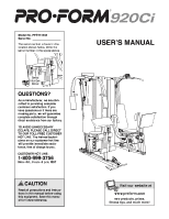
USER’S MANUAL
Model No. PFSY74490
Serial No.
The serial number is found in the
location shown below. Write the
serial number in the space above.
CAUTION
Read all precautions and instruc-
tions in this manual before using
this equipment. Save this manu-
al for future reference.
Serial
Number
Decal
QUESTIONS?
As a manufacturer, we are com-
mitted to providing complete
customer satisfaction. If you
have questions or if there are
missing parts, we will guarantee
complete satisfaction through
direct assistance from our factory.
TO AVOID UNNECESSARY
DELAYS, PLEASE CALL DIRECT
TO OUR TOLL-FREE CUSTOMER
HOT LINE. The trained techni-
cians on our customer hot line
will provide immediate assis-
tance, free of charge to you.
CUSTOMER HOT LINE:
1-800-999-3756
Mon.–Fri., 6 a.m.–6 p.m. MST
Visit our website at
www.proform.com
new products, prizes,
fitness tips, and much more!