ProForm 970 Ci English Manual
ProForm 970 Ci Manual
 |
View all ProForm 970 Ci manuals
Add to My Manuals
Save this manual to your list of manuals |
ProForm 970 Ci manual content summary:
- ProForm 970 Ci | English Manual - Page 1
PRO•FORM® Model No. PF897030 Serial No. CAST IRON RESISTANCE c 3 e Serial Number 3756 Mon.-Fri., 6 a.m.-6 p.m. MST CAUTION! Read all safety precautions and instructions in this manual before using this equipment. Save this manual for future reference. PATENT PENDING 0 C 0 e , ii------ 0 0III - ProForm 970 Ci | English Manual - Page 2
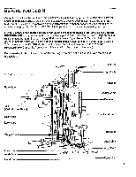
IMPORTANT SAFETY PRECAUTIONS BEFORE YOU BEGIN ASSEMBLY USING THE PROFORM 970 CI TROUBLE-SHOOTING AND MAINTENANCE ORDERING REPLACEMENT PARTS LIMITED WARRANTY before using the weight training system. 1. Read all instructions in this manual and in the accompanying literature before using the weight - ProForm 970 Ci | English Manual - Page 3
size and strength, the PROFORM 970 CI will help you to achieve the specific results you want. For your safety and benefit, read this manual and the accompanying literature before using the PROFORM 970 Cl. If you have additional questions, please call our Customer Service Department tollfree at 1-800 - ProForm 970 Ci | English Manual - Page 4
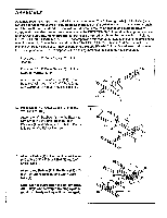
are oriented as shown in the drawings. Refer to the PART IDENTIFICATION (ID) CHART accompanying this manual for help identifying the small parts used in assembly. Due to the size and weight of the PROFORM 970 CI, it should be assembled in the location where it will be used. Place all parts of the - ProForm 970 Ci | English Manual - Page 5
4. Press two 1 1/2" x 1 1/2" Inner Caps (41) into 4 the Butterfly Upright (77). Press a 2" x 2" Inner Cap (11) into the Butterfly Upright. Press two 2" x 2" Outer Caps (10) onto the Stabilizer (19). Hold the Butterfly Upright (77) on top of the Stabilizer (19) as shown. Attach the Butterfly Upright - ProForm 970 Ci | English Manual - Page 6
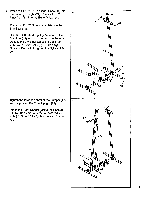
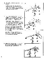
hole in the Frame Top (80). Thread a 3/8" Nylock Nut (1) onto the Bolt. Insert a 3/8" x 3" Bolt (7) through the upper hole in the Butterfly Support (73), the Butterfly Upright (77) and the lower hole in the Frame Top (80). Thread a 3/8" Nylock Nut (1) onto the Bolt. Insert a 3/8" x 2 3/4" Bolt - ProForm 970 Ci | English Manual - Page 7
Bolts (7) and 3/8" Nylock Nuts (1). Do not fully tighten the Nylock Nuts yet. 76 1 ! 83 .- .. 11. Slide the two Weight Bumpers (50) onto the Weight Guides (56). Insert the Weight Guides 11 into the indicated holes in the Base (89). 12. Slide the nineteen Weights (84) down onto 12 the Weight - ProForm 970 Ci | English Manual - Page 8
Top (78) with a 3/8" x 2" Shank Bolt (8) and 3/8" Nylock Nut (1). 78 • 11 11 .1., -• 1 - I ''' 9 8 15. Slide the Weight Guide Top (78) onto the 15 upper ends of the Weight Guides (56). Attach the Weight Guide Top to the Frame Top (80) and the VKR Upright (76) with two 3/8" x 3" Bolts (7) and - ProForm 970 Ci | English Manual - Page 9
18. Attach the VKR Backrest (66) to the center of the VKR Frame (67) with two 8mm x 3/4" Bolts (6) and 8mm Washers (4). Attach the two VKR Armrests (65) to the VKR Frame (67) with 3/8" x 2" Bolts (17) and 3/8" Washers (2). 19. Insert a 3/8" x 3 1/2" Shank Bolt (25) into one side of the Adjuster (61 - ProForm 970 Ci | English Manual - Page 10
21. Grease the insides of the two 1/2" Bushings (23) in the Frame Top (80). Slide the Press Arm (88) onto the Frame Top (80). Align the two Thick 5/8" Bushings (26) in the Adjuster (61) with the 1/2" Bushings (23) in the Frame Top. Make sure that the Press Arm is turned so the long end of the - ProForm 970 Ci | English Manual - Page 11
23. Attach the Lat Bar Holder (49) to the Frame Top (80) with the two 3/16" Screws (40). 23 40 49 80 ..•.. `,F..f,. 24. Attach the Small Seat Frame (36) to the Butterfly Upright (77) with two 3/8" x 2 3/4" Bolts (79), 3/8" Washers (2) and 3/8" Nylock Nuts (1). Note: The Butterfly Upright has two - ProForm 970 Ci | English Manual - Page 12
27. Using an adjustable wrench, tighten the shaft of a Lock Knob (46) into the bracket on the Front Upright (72) as shown. Press two Tube Caps (39) into a Pad Tube (58). Insert the Pad Tube (58) into the Front Upright (72) and center it. Slide a 6" Foam Pad (59) onto each end of the Pad Tube. Note: - ProForm 970 Ci | English Manual - Page 13
31. Press two 1" x 2" Inner Caps (5) into the Large Seat Post (69). Wet the ends of the "U" Handle (68) with soapy water and slide a Small Handgrip (14) onto each end. Attach the "U" Handle (68) and the Large Seat Post (69) to the Large Seat (63) with two 3/8" x 2" Bolts (17), two 3/8" Washers (2), - ProForm 970 Ci | English Manual - Page 14
34. Turn the Lock Knob (46) on the side of the Front Upright (72) counterclockwise and pull it outward (see page 21). Insert the Small Backrest Post (34) into the Front Upright and adjust it to the desired position. Release the Lock Knob and turn it clockwise until it stops. Make sure that the pin - ProForm 970 Ci | English Manual - Page 15
one of the Pulleys (9) on one of the Swivel Brackets (51) as shown. Route the end of Cable #1 (91) over the Pulley (9) on the Weight Guide Top (78). Thread the bolt on the end of Cable #1 (91) about halfway into the Weight Selector (57). ••• J61 91 etc 72 9 0. a 90 8 I'll II - ProForm 970 Ci | English Manual - Page 16
) into the Right Butterfly Arm (75). 43 74 Grease the threaded post on the Right Butterfly Arm (75). Insert the post up through the Butterfly Support (73). Tighten a 1/2" Nylock Nut (22), with an 11/16" Washer (21), onto the post. Do not overtighten the Nylock Nut. Wet the lower end of - ProForm 970 Ci | English Manual - Page 17
44. Find Cable #2 (92). Attach one end of the Cable to the Right Butterfly Arm (75) with an 8mm x 3/4" Bolt (6), two 8mm Washers (4) and an 8mm Nylock Nut (42). Do not overtighten the Nylock Nut. The Cable must swivel freely. 44 41 i 42 1l'ir:_„„4 4 6 92 75 45. Route the other end of Cable - ProForm 970 Ci | English Manual - Page 18
48. Route the end of Cable #4 (94) over the 48 lowerPulley (9) on,the indicated Swivel Bracket (51). Route the end of Cable #4 (94) under the indicated Pulley (9) on the Base (89). Route the end of Cable #4 (94) over the lower Pulley (9) on the other Swivel Bracket (51). Route the end of Cable - ProForm 970 Ci | English Manual - Page 19
will be explained in USING THE PROFORM 970 CI, beginning on page 20 of this owner's manual. 53. Before using the PROFORM 970 CI, test the cables and pulleys cables does not move smoothly, locate and correct the problem before using the PROFORM 970 Cl.MPORTANT: If the cables are not properly routed, - ProForm 970 Ci | English Manual - Page 20
USING THE PROFORM 970 CI The Instructions below describe how each component of the PROFORM 970 CI can be adjusted. See the EXERCISE GUIDE accompanying this owner's manual to see how the PROFORM 970 CI should be set up for each individual exercise. CHANGING THE WEIGHT SETTING The weight setting can - ProForm 970 Ci | English Manual - Page 21
ADJUSTING THE HEIGHT OF THE LARGE SEAT 1. Turn the Lock Knob (46) on the side of the Leg Lever Frame (70) counterclockwise until it turns freely. Pull the Lock Knob outward. 2. Raise or lower the Large Seat Post (69) to the desired height. CAUTION: Be careful to avoid pinching your hand. 3. Release - ProForm 970 Ci | English Manual - Page 22
USING THE HIGH CABLE The Lat Bar (90) can be attached to the high cable with a Cable Clip (48). For certain exercises, the Long Chain (82) should be attached between the Lat Bar and the high cable with two Cable Clips. The length of the Chain between the Lat Bar and the high cable can be adjusted by - ProForm 970 Ci | English Manual - Page 23
TROUBLE-SHOOTING AND MAINTENANCE Inspect and tighten all parts of the PROFORM 970 CI regularly. Replace any worn parts immediately. The PROFORM 970 CI . If the cables cannot be tightened enough by turning the bolt, refer to the instructions below. I II 91 57 0 0 Find the bolt on the end of Cable - ProForm 970 Ci | English Manual - Page 24
(PROFORM® 970 CI weight training system). 3. The SERIAL NUMBER of the product (see the front cover of this manual). 4. The KEY NUMBER and DESCRIPTION of the part(s) (see the PART LIST/EXPLODED DRAWING accompanying this manual). LIMITED WARRANTY Proform Fitness Products, Inc. ("PROFORM"), warrants
-
 1
1 -
 2
2 -
 3
3 -
 4
4 -
 5
5 -
 6
6 -
 7
7 -
8
-
9
-
10
-
11
-
12
-
13
-
14
-
15
-
16
-
17
-
18
-
19
-
20
-
21
-
22
-
23
-
24
 |
 |

PRO•FORM
®
Model
No.
PF897030
Serial
No.
c
e
Decal
3
Serial
Number
QUESTIONS?
As
a
manufacturer,
we
are
committed
to
providing
you
complete
customer
satisfac-
tion.
If
you
have
questions,
or
find
there
are
missing
or
damaged
parts,
we
will
guarantee
you
complete
-
satisfaction
through
direct
assistance
from
our
factory.
TO
AVOID
UNNECESSARY
DELAYS,
PLEASE
CALL
DIRECT
TO
OUR
TOLL
-FREE
CUSTOMER
HOT
LINE.
The
trained
technicians
on
our
customer
hot
line
will
provide
immediate
assis-
tance,
free
of
charge
to
you.
CUSTOMER
HOT
LINE:
1-800-999-3756
Mon.
-Fri.,
6
a.m.-6
p.m.
MST
CAUTION!
Read
all
safety
precautions
and
instructions
in
this
manual
before
using
this
equipment.
Save
this
manual
for
future
reference.
PATENT
PENDING
CAST
IRON
RESISTANCE
0
C
0
e
,
III.—
ii
------
0
0
0.
--•■.__
-
•
-
mil
---
_
_to
6
limolli
ll
%a
'I.
OWNER'S
MANUAL