ProForm Fusion 6.0 Lx English Manual - Page 26
Using The Leg Lever Lock
 |
View all ProForm Fusion 6.0 Lx manuals
Add to My Manuals
Save this manual to your list of manuals |
Page 26 highlights
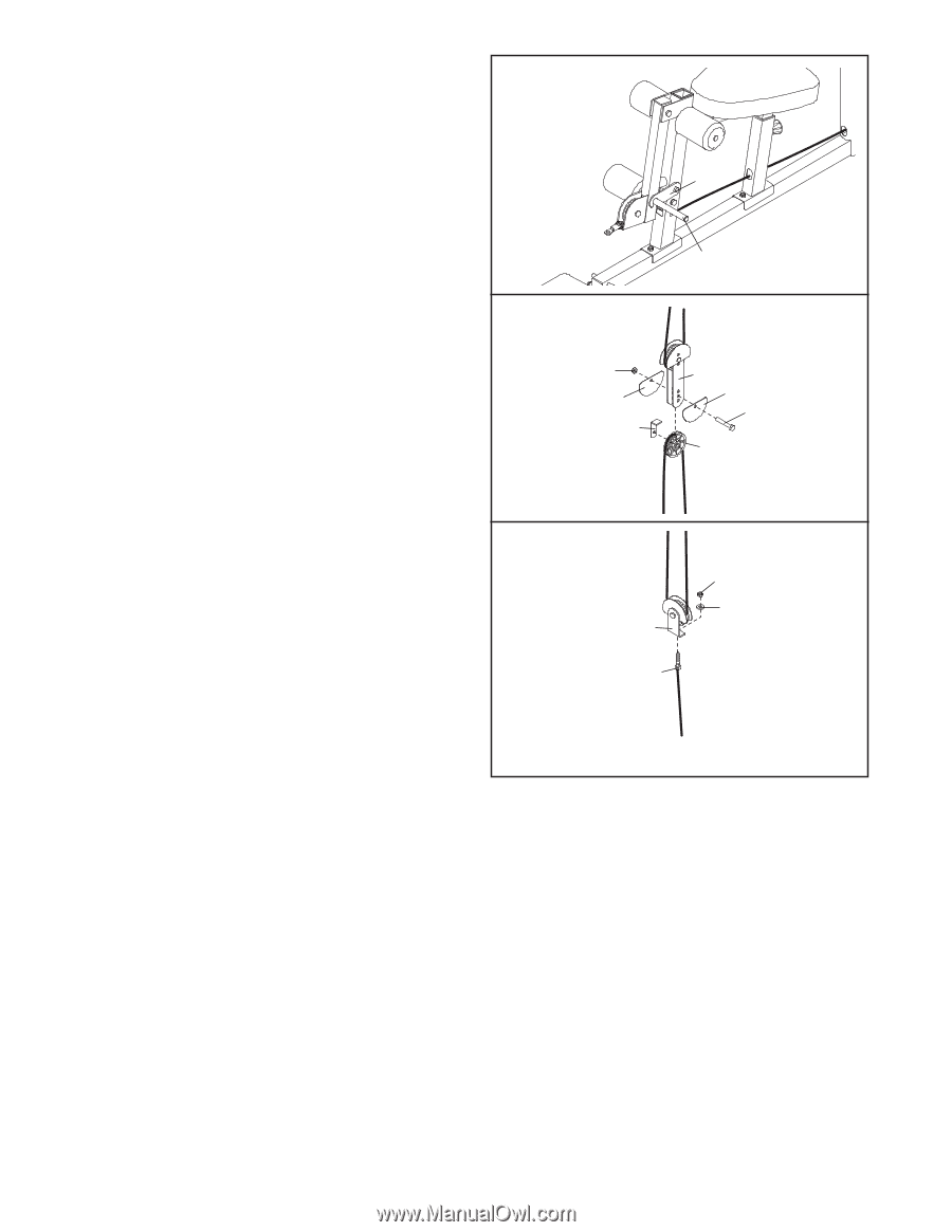
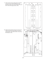
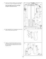
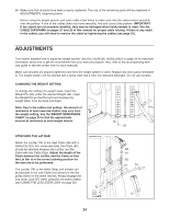
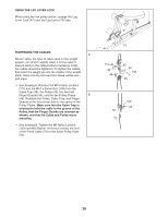
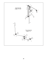
USING THE LEG LEVER LOCK When using the low pulley station, engage the Leg Lever Lock (47) onto the Leg Lever (15) tube. TIGHTENING THE CABLES A Woven cable, the type of cable used on the weight system, can stretch slightly when it is first used. If there is slack in the cables before resistance is felt, the cables should be tightened. To tighten the cables, first insert the weight pin into the middle of the weight stack. Slack can be removed from these cables several ways: • See drawing A. Remove the M10 Nylon Locknut (111) and the M10 x 50mm Bolt (106) from the Cable Trap (48), the Pulley (43), the two Half Finger Guards (46), and the two Pulley Plates B (49). Reattach the Pulley, Cable Trap, and Finger Guards at the next closer hole to the center of the Pulley Plates. Make sure that the Cable Trap is oriented to hold the cable in the groove of the Pulley, that the Finger Guards are oriented as shown, and that the Cable and Pulley move smoothly. • See drawing B. Tighten the M6 Nylon Locknut (103) and M6 Washer (114) that connect the end of the Press Cable (72) to the Small Pulley Plate (50). 47 15 111 46 48 49 46 106 43 103 114 50 72 26
-
 1
1 -
2
-
3
-
4
-
5
-
6
-
7
-
8
-
9
-
10
-
11
-
12
-
13
-
14
-
15
-
16
-
17
-
18
-
19
-
20
-
 21
21 -
 22
22 -
 23
23 -
 24
24 -
 25
25 -
 26
26 -
 27
27 -
 28
28 -
 29
29 -
 30
30 -
 31
31 -
32
-
33
-
34
-
35
-
36
-
37
-
38
-
39
-
40
 |
 |