ProForm Fusion 6.0 Lx English Manual - Page 6
Frame Assembly
 |
View all ProForm Fusion 6.0 Lx manuals
Add to My Manuals
Save this manual to your list of manuals |
Page 6 highlights
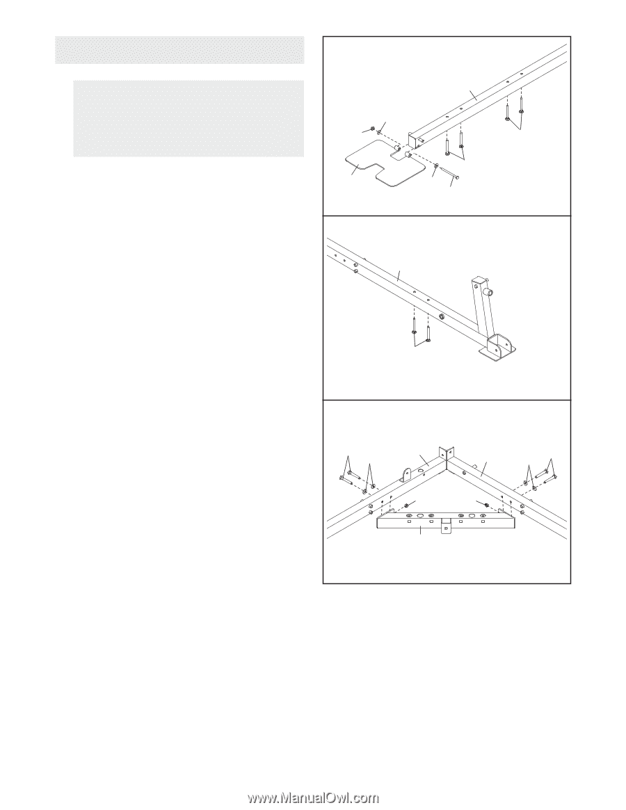
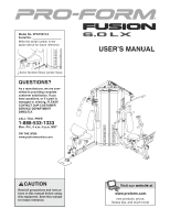
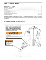
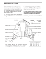
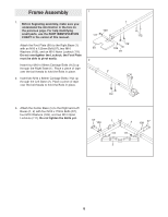
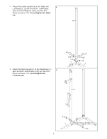
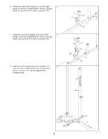
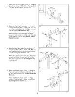
Frame Assembly 1 1. Before beginning assembly, make sure you understand the information in the box on the previous page. For help identifying small parts, use the PART IDENTIFICATION CHART in the center of this manual. 109 111 1 112 Attach the Foot Plate (90) to the Right Base (1) with an M10 x 120mm Bolt (97), two M10 Washers (109), and an M10 Nylon Locknut (111). Do not overtighten the Locknut; the Foot Plate must be able to pivot easily. Insert four M10 x 80mm Carriage Bolts (112) up through the Right Base (1). Place a piece of tape over the bolt heads to hold the Bolts in place. 90 2 112 109 97 2 2. Insert two M10 x 80mm Carriage Bolts (112) up through the Left Base (2). Place a piece of tape over the bolt heads to hold the Bolts in place. 112 3. Attach the Center Base (5) to the Right and Left Bases (1, 2) with four M10 x 70mm Bolts (57), four M10 Washers (109), and two M10 Nylon Locknuts (111). Do not tighten the Bolts yet. 3 57 109 1 2 57 109 111 111 5 6
-
 1
1 -
 2
2 -
 3
3 -
 4
4 -
 5
5 -
 6
6 -
 7
7 -
 8
8 -
 9
9 -
 10
10 -
 11
11 -
 12
12 -
13
-
14
-
15
-
16
-
17
-
18
-
19
-
20
-
21
-
22
-
23
-
24
-
25
-
26
-
27
-
28
-
29
-
30
-
31
-
32
-
33
-
34
-
35
-
36
-
37
-
38
-
39
-
40
 |
 |