ProForm Perspective 1000 Elliptical English Manual - Page 8
the Base 1. Attach the Left Roller Leg with an
 |
View all ProForm Perspective 1000 Elliptical manuals
Add to My Manuals
Save this manual to your list of manuals |
Page 8 highlights
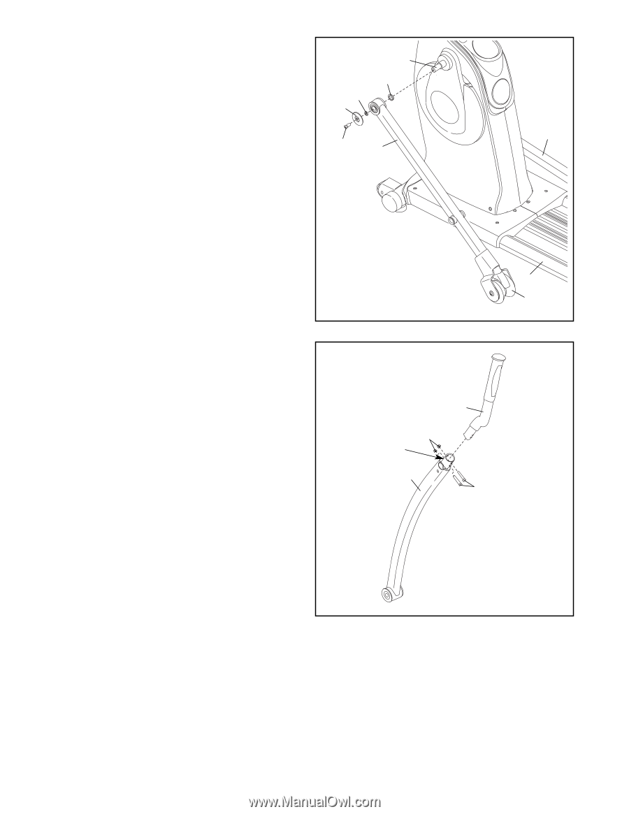
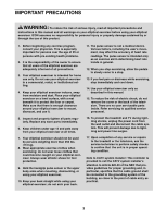
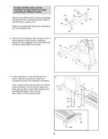
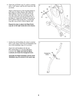
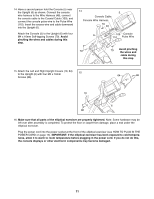
6. Orient the Left Roller Leg (12), which is marked 6 with a "Left" sticker, near the left Crank Arm (36) as shown. 36 98 Apply a small amount of the included grease to both sides of a Wave Washer (98). Slide the Wave Washer onto the end of the left Crank 94 30 Arm (36). Next, slide the Left Roller Leg (12) onto the Crank Arm and set the Roller (22) on the Base (1). Attach the Left Roller Leg with an 91 12 21 M10 x 20mm Patch Screw (91), a Crank Axle Cap (30), and an M10 x 25mm Washer (94). Repeat this step to attach the Right Roller Leg (21) to the right Crank Arm (not shown). 1 22 7. Identify the Left Handlebar (8), which is marked with a "Left" sticker. Insert the Left Handlebar into 7 one of the Handlebar Legs (11) as shown. Attach the Left Handlebar (8) with two M8 x 42mm Bolts (71) and two M8 Nylon Locknuts (96). Make sure that the Nylon Locknuts are inside the hexagonal holes. Assemble the Right Handlebar and the other Handlebar Leg (not shown) in the same way. Hexagonal 96 Holes 11 8 71 8
-
 1
1 -
2
-
 3
3 -
 4
4 -
 5
5 -
 6
6 -
 7
7 -
 8
8 -
 9
9 -
 10
10 -
 11
11 -
 12
12 -
 13
13 -
14
-
15
-
16
-
17
-
18
-
19
-
20
-
21
-
22
-
23
-
24
-
25
-
26
-
27
-
28
-
29
-
30
-
31
-
32
 |
 |