ProForm Xp 130 Elliptical English Manual - Page 8
Left Upper Body Arm. Attach the Left Handlebar with two
 |
View all ProForm Xp 130 Elliptical manuals
Add to My Manuals
Save this manual to your list of manuals |
Page 8 highlights
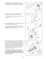
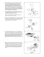
9. Identify the Left Handlebar (8) and the Left Upper Body 9 Arm (11), which are marked with stickers. Orient the Left Handlebar (8) and the Left Upper Body Arm (11) as shown, and insert the Left Handlebar into the Left Upper Body Arm. Attach the Left Handlebar with two M8 x 43mm Button Bolts (78) and two M8 Jamnuts (79). Make sure that the Jamnuts are in the hexagonal holes in the Left Upper Body Arm. Attach the Right Handlebar (9) to the Right Upper Body Arm (12) in the same way. 9 8 79 78 79 78 12 11 10. Insert the Pivot Axle (74) into the Upright (3) and center it. Apply a generous amount of the included grease to the Pivot Axle. Orient the Left Upper Body Arm (11) as shown, and slide it onto the left end of the Pivot Axle (74). Slide the Right Upper Body Arm (12) onto the right end of the Pivot Axle. Tighten an M8 x 23mm Button Screw (84) with an M8 Washer (88) and a Wave Washer (111) into each end of the Pivot Axle (74). Make sure that the Wave Washers are on the ends of the Pivot Axle. 11. Hold the Left Front Handlebar Cover (18) and the Left Rear Handlebar Cover (19) around the Left Upper Body Arm (11). Attach the Handlebar Covers with three M4 x 32mm Round Head Screws (105). Attach the Right Front Handlebar Cover (20) and the Right Rear Handlebar Cover (21) around the Right Upper Body Arm (12) in the same way. 10 Grease 74 88 11 84 111 11 105 18 11 8 3 88 84 111 12 20 21 12 19
-
 1
1 -
2
-
 3
3 -
 4
4 -
 5
5 -
 6
6 -
 7
7 -
 8
8 -
 9
9 -
 10
10 -
 11
11 -
 12
12 -
 13
13 -
14
-
15
-
16
-
17
-
18
-
19
-
20
-
21
-
22
-
23
-
24
-
25
-
26
-
27
-
28
 |
 |
