ProForm Xp 580 Crosstrainer Treadmill User Manual - Page 6
Assembly - belts
 |
View all ProForm Xp 580 Crosstrainer Treadmill manuals
Add to My Manuals
Save this manual to your list of manuals |
Page 6 highlights
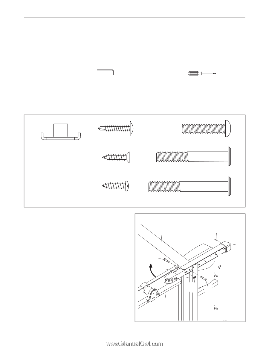
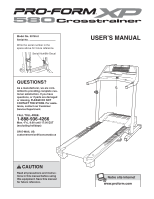
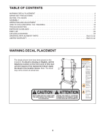
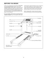
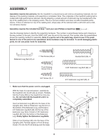
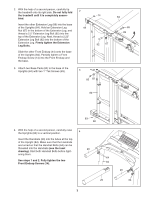
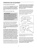
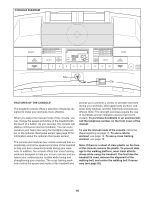
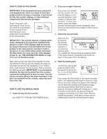
ASSEMBLY Assembly requires two persons. Set the treadmill in a cleared area and remove all packing materials. Do not dispose of the packing materials until assembly is completed. Note: The underside of the treadmill walking belt is coated with high-performance lubricant. During shipping, a small amount of lubricant may be transferred to the top of the walking belt or the shipping carton. This is a normal condition and does not affect treadmill performance. If there is lubricant on top of the walking belt, simply wipe off the lubricant with a soft cloth and a mild, non-abrasive cleaner. Assembly requires the included hex keys and your own Phillips screwdriver . Use the drawings below to identify the assembly hardware. The number in parentheses below each drawing is the key number of the part, from the PART LIST near the end of the manual. The number after the parentheses shows the quantity needed for assembly. Note: If a part is not in the parts bag, check to see if it is preattached to one of the parts to be assembled. Extra hardware may be included. To avoid damaging plastic parts, do not use power tools for assembly. Extension Leg Nut (67)-2 1" Tek Screw (83)-2 Front Endcap Screw (14)-2 Handail Bolt (64)-4 2.25" Extension Leg Bolt (92)-2 3/4" Screw (2)-2 2.5" Extension Leg Bolt (65)-2 1. Make sure that the power cord is unplugged. 1 With the help of a second person, carefully tip the treadmill onto its left side as shown. Partially 84 fold the Frame (58) so the treadmill is more sta- ble. Do not fully fold the treadmill until it is completely assembled. Insert an Extension Leg (89) into the base of the Uprights (84). Hold an Extension Leg Nut (67) in the bottom of the Extension Leg, and thread a 2.5" Extension Leg Bolt (65) into the top of the Extension Leg. Next, thread a 2.25" Extension Leg Bolt (92) into the bottom of the Extension Leg. Firmly tighten the Extension Leg Bolts. 65 89 Slide a Front Endcap (44) onto the base of the 58 Uprights (84). Partially tighten a Front Endcap Screw (14) into the Front Endcap and the base. 14 44 67 92 6
-
 1
1 -
 2
2 -
 3
3 -
 4
4 -
 5
5 -
 6
6 -
 7
7 -
 8
8 -
 9
9 -
 10
10 -
 11
11 -
 12
12 -
13
-
14
-
15
-
16
-
17
-
18
-
19
-
20
-
21
-
22
-
23
-
24
-
25
-
26
-
27
-
28
 |
 |