ProForm Xp 600 S English Manual
ProForm Xp 600 S Manual
 |
View all ProForm Xp 600 S manuals
Add to My Manuals
Save this manual to your list of manuals |
ProForm Xp 600 S manual content summary:
- ProForm Xp 600 S | English Manual - Page 1
or if there are missing or damaged parts, please call the telephone number on the warranty card accompanying this manual or contact the establishment where you purchased this product. USER'S MANUAL CAUTION Read all precautions and instructions in this manual before using this equipment. Save this - ProForm Xp 600 S | English Manual - Page 2
PART LIST/EXPLODED DRAWING are attached in the center of this manual. Remove the PART IDENTIFICATION CHART and PART LIST/EXPLODED DRAWING the warranty card accompanying this manual and order a free replacement decal. Apply the decal in the location shown. PROFORM is a registered trademark of ICON IP - ProForm Xp 600 S | English Manual - Page 3
instructions in this manual before using the weight system. Use the weight system only as described in this manual lat bar. 8. The weight system is designed to support a maximum user weight of 300 pounds. 16. If with pre-existing health problems. Read all instructions before using. ICON assumes - ProForm Xp 600 S | English Manual - Page 4
YOU BEGIN Thank you for selecting the versatile PROFORM® XP 600 S weight system. The weight system offers an to the weight system (see the front cover of this manual for the location of the decal). Before reading further, please review the drawing below and familiarize yourself with the parts that - ProForm Xp 600 S | English Manual - Page 5
assembly, we have included a PART IDENTIFICATION CHART in the center of this manual. Place the chart on the floor and use it to easily identify parts unless instructed to do otherwise. QUESTIONS? If you have questions after reading these assembly instructions, see the front cover of this manual. - ProForm Xp 600 S | English Manual - Page 6
1 1. Before beginning assembly, make sure you understand the information in the box on page 5. See the PART IDENTIFICATION CHART in the center of this manual for help identifying small parts. Insert four M8 x 75mm Carriage Bolts (69) up through the Right Base (1). Note: It may be helpful to place - ProForm Xp 600 S | English Manual - Page 7
5. See drawing A. Attach the Right Upright (2) to 5A the Right Base (1) with the two indicated M8 x 75mm Carriage Bolts (69) and two M8 Nylon Locknuts (91). Do not tighten the Locknuts yet. See drawing B. Attach the Left Upright (26) to the Left Base (25) with the two indicated M8 x 75mm - ProForm Xp 600 S | English Manual - Page 8
M8 Nylon Locknuts 98 82 27 (91). Do not tighten the Locknuts yet. 25 91 91 8. Orient the Weight Guides (44) with the indicated 8 holes closer to the bottom. Attach the Weight Guides inside of the Center Base (52) with two M8 x 78mm Bolts (82), four M8 Washers (98), and two M8 - ProForm Xp 600 S | English Manual - Page 9
in the top Weight. Grease the indicated holes in the Top Weight (56) with an included grease pack. Slide the Top Weight onto the Weight Guides (44). 44 56 Grease Pin 47 Groove 46 55 Pin 45 45 Holes 10. Attach the Right Top Frame (5) to the Right 10 Upright (2) with - ProForm Xp 600 S | English Manual - Page 10
(5) with four M8 x 78mm Bolts (82), two M8 Washers (98), a Support Plate (31), and four M8 Nylon Locknuts (91). Do not tighten the Locknuts yet (36) to the Left Upright (26) with two M8 x 78mm Bolts (82), a Support 13 Plate (31), and two M8 Nylon Locknuts (91). Do not tighten the Locknuts yet - ProForm Xp 600 S | English Manual - Page 11
16. Attach the Leg Bumper (59) to the Right Seat Frame (3) with an M4 x 16mm Self-tapping Screw (89) and an M4 Washer (96). Grease an M10 x 75mm Bolt (60). Attach the Leg Lever (4) to the Right Seat Frame (3) with the Bolt and an M10 Nylon Locknut (90). Make sure the "U"-rod is on the indicated side - ProForm Xp 600 S | English Manual - Page 12
19. Attach a Press Arm (30) to the Press Frame (29) 19 with two M8 x 69mm Bolt (86) and two M8 Nylon Locknuts (91). Repeat this step with the other Press Arm (30). 86 30 20. Grease an M10 x 108mm Bolt (72). Attach the 20 Leg Press Frame (28) to the Left Base (25) with the Bolt and an M10 - ProForm Xp 600 S | English Manual - Page 13
23. Wrap the Press Cable (109) around a 90mm Pulley (63). Attach the Pulley, two Half Finger Guards (66), a Cable Trap (68), and an M10 Washer (99) to the Left Seat Frame (27) with an M10 x 103mm Bolt (22) and an M10 Nylon Locknut (90). Make sure the Cable Trap and the Finger Guards are oriented as - ProForm Xp 600 S | English Manual - Page 14
27. Wrap the Press Cable (109) around a "V"-pulley (62). Attach the "V"-pulley, two Half Finger Guards (66), a Large Cable Trap (111), and an M10 Washer (99) inside the bracket on the Left Upright (26) with an M10 x 65mm Bolt (77) and an M10 Nylon Locknut (90). Make sure the Cable Trap and Finger - ProForm Xp 600 S | English Manual - Page 15
31. Attach the end of the Press Cable (109) to a "U"- 31 bracket (50) with an M8 Washer (98) and an M8 Nylon Locknut (91). Note: Do not completely tighten the Locknut; it should be tightened so that only two threads of the Cable show past the Locknut, as shown in the inset drawing. 32. - ProForm Xp 600 S | English Manual - Page 16
36. Grease an M8 x 22mm Shoulder Bolt (39). Attach 36 the Butterfly Cable (106) to the Right Butterfly Arm (7) with the Bolt and an M8 Nylon Locknut (91). Make sure the flat edge of the Cable is against the Butterfly Arm. 37. Identify the Short Cable (108). Attach the Cable 37 to the M8 x - ProForm Xp 600 S | English Manual - Page 17
41. Route the Weight Cable (110) over a 90mm 41 Pulley (63) and down through the Right Top Frame (5). Attach the Pulley inside the Top Frame with an M10 x 80mm Bolt (75), two M10 Washers (99), two M10 x 19mm Spacers (102), and an M10 Nylon Locknut (90). 75 99 102 99 90 63 110 5 42. Wrap - ProForm Xp 600 S | English Manual - Page 18
46. Identify the Ab Cable (107). Route the small ball on the Cable through the Leg Lever (4) and the Right Seat Frame (3). Make sure the Cable is over the rod in the Seat Frame. Attach a 90mm Pulley (63) inside the Leg Lever (4), over the Ab Cable (107), with an M10 x 65mm Bolt (77), two M10 Washers - ProForm Xp 600 S | English Manual - Page 19
50. Wrap the Ab Cable (107) under a 90mm Pulley 50 (63). Attach the Pulley, a Cable Trap (68), and two Half Finger Guards (66) to the Right Base (1) with an M10 x 50mm Bolt (64) and an M10 Nylon Locknut (90). Make sure the Cable Trap and Finger Guards are oriented as shown. 90 66 107 63 1 - ProForm Xp 600 S | English Manual - Page 20
55. Wrap the Ab Cable (107) over a 90mm Pulley 55 (63). Attach the Pulley and the two Quarter Finger Guards (105) to the Right Upright (2) with an M10 x 108mm Bolt (72), an M10 Washer (99), and an M10 Nylon Locknut (90). Make sure that the rod is inserted through both Finger Guards and is - ProForm Xp 600 S | English Manual - Page 21
59. Attach the Butterfly Backrest (9) to the Right 59 Upright (2) with four M6 x 16mm Screws (88). 9 88 2 88 60. Press the two Shroud Covers (11) onto the 60 Shroud (10). Attach the Shroud to the Right Top Frame (5) and the Center Base (52) with four M6 x 22mm Bolts (87), four M6 Washers ( - ProForm Xp 600 S | English Manual - Page 22
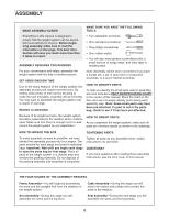
pulleys. If one of the cables does not move smoothly, find and correct the problem. IMPORTANT: If the cables are not properly installed, they may be damaged when weight is used. See the CABLE DIAGRAMS on pages 26 and 27 of this manual for proper cable routing. If there is any slack in the cables, you - ProForm Xp 600 S | English Manual - Page 23
the EXERCISE GUIDELINES on page 29 for important information about how to get the most benefit from your exercise program. Also, see the accompanying exercise guide to see the correct form for each exercise. Make sure all parts are properly tightened each time the weight system is used. Replace any - ProForm Xp 600 S | English Manual - Page 24
Frame (53). Make sure the Knob is fully tightened. LOCKING THE WEIGHT STACK Lock the weight stack by inserting the Lock Pin (65) through a Weight Guide (44) and securing the Lock (48) onto the Lock Pin. 26 53 113 43 44 48 65 24 - ProForm Xp 600 S | English Manual - Page 25
: The actual resistance at each station may vary due to differences in individual weight plates as well as friction between the cables, pulleys, and weight guides. WEIGHT Top 1 2 3 4 5 6 7 8 HIGH PULLEY (lbs.) 10 25 38 54 67 84 97 105 122 BUTTERFLY ARM (lbs.) 16 30 45 51 60 73 88 93 - ProForm Xp 600 S | English Manual - Page 26
CABLE DIAGRAMS The cable diagrams below show the proper routing of the Butterfly Cable (106), the Ab Cable (107), the Short Cable (108), the Press Cable (109), and the Weight Cable (110). Use the diagram to make sure that the cables and the cable traps have been assembled correctly. If the cables - ProForm Xp 600 S | English Manual - Page 27
9 10 2 5 1 4 3 Weight Cable (110) Length: 12 feet 1 inch 6 84 Press Cable (109) Length: 22 feet 6 inches 6 7 5 3 2 1 27 - ProForm Xp 600 S | English Manual - Page 28
twisted. Remove the cable and reinstall it. If the cables need to be replaced, see the part ordering information on the back cover of this manual. 28 - ProForm Xp 600 S | English Manual - Page 29
and moving only the appropriate parts of the body. Exercising in an uncontrolled manner will leave you feeling exhausted. On the exercise guide accompanying this manual you will find photographs showing the correct form for several exercises, and a list of the muscles affected. See the muscle chart - ProForm Xp 600 S | English Manual - Page 30
each workout is an effective way to increase flexibility. STAYING MOTIVATED For motivation, keep a record of each workout. The chart on page 31 of this manual can be photocopied and used to schedule and record your workouts. List the date, the exercises performed, the weight used, and the numbers of - ProForm Xp 600 S | English Manual - Page 31
MONDAY Date: // EXERCISE WEIGHT SETS REPS TUESDAY Date: // WEDNESDAY Date: // AEROBIC EXERCISE EXERCISE WEIGHT SETS REPS THURSDAY Date: // FRIDAY Date: // AEROBIC EXERCISE EXERCISE WEIGHT SETS REPS Make photocopies of this page for scheduling and recording your workouts. 31 - ProForm Xp 600 S | English Manual - Page 32
SAVE THIS PART IDENTIFICATION CHART FOR FUTURE REFERENCE - ProForm Xp 600 S | English Manual - Page 33
number of the part, from the PART LIST in the center of this manual. Note: Some small parts may have been pre-attached. If a -attached. If a part is missing, call the telephone number on the warranty card accompanying this manual. M6 Nylon Locknut (92) M8 Nylon Locknut (91) M10 x 75mm Bolt (60) M8 - ProForm Xp 600 S | English Manual - Page 34
M6 x 35mm Screw (78) M8 x 22mm Shoulder Bolt (39) M6 x 22mm Bolt (87) M6 x 16mm Screw (88) M4 x 16mm Self-tapping Screw (89) M8 x 75mm Carriage Bolt (69) M10 x 77mm Bolt (76) M8 x 78mm Bolt (82) M10 x 80mm Bolt (75) M8 x 86mm Shoulder Bolt (37) M10 x 85mm Bolt (74) M8 x 96mm Bolt (83) M10 x 103mm - ProForm Xp 600 S | English Manual - Page 35
Seat Frame 28 1 Leg Press Frame 29 1 Press Frame 30 2 Press Arm 31 2 Support Plate 32 2 Press Handle 33 2 M12 Washer 34 2 Press Arm Cap 35 1 Short Trap 20mm x 40mm Inner Cap Press Backrest User's Manual Exercise Guide Grease Packet Allen Wrench Note: "#" indicates a non- - ProForm Xp 600 S | English Manual - Page 36
SAVE THIS PART LIST/EXPLODED DRAWING FOR FUTURE REFERENCE 81 - ProForm Xp 600 S | English Manual - Page 37
EXPLODED DRAWING A-Model No. PFANSY9825.1 R0306A 80 68 63 90 99 75 102 63 82 102 58 13 99 63 98 98 90 75 98 98 11 97 97 87 87 99 102 5 92 92 58 63 90 90 73 104 80 19 102 90 39 106 99 74 68 99 91 80 63 62 111 110 74 91 91 23 104 10 7 14 91 100 90 23 42 90 - ProForm Xp 600 S | English Manual - Page 38
EXPLODED DRAWING B-Model No. PFANSY9825.1 R0306A 31 19 36 82 98 82 63 82 66 90 66 93 94 81 95 100 34 82 91 82 98 91 110 49 98 98 91 91 33 91 56 84 90 31 66 19 61 66 100 34 84 63 64 91 66 68 63 90 101 99 51 66 81 79 90 99 32 101 32 86 30 30 66 101 99 77 66 90 63 - ProForm Xp 600 S | English Manual - Page 39
the following information: 1. the MODEL NUMBER of the product (PFANSY9825.1) 2. the NAME of the product (PROFORM XP 600 S weight system) 3. the SERIAL NUMBER of the product (see the front cover of this manual) 4. the KEY NUMBER and DESCRIPTION of the part(s) (see the PART LIST and EXPLODED DRAWING
-
 1
1 -
 2
2 -
 3
3 -
 4
4 -
 5
5 -
 6
6 -
 7
7 -
8
-
9
-
10
-
11
-
12
-
13
-
14
-
15
-
16
-
17
-
18
-
19
-
20
-
21
-
22
-
23
-
24
-
25
-
26
-
27
-
28
-
29
-
30
-
31
-
32
-
33
-
34
-
35
-
36
-
37
-
38
-
39
 |
 |

QUESTIONS?
As a manufacturer, we are
committed to providing com-
plete customer satisfaction.
If you have questions, or if
there are missing or damaged
parts, please call the tele-
phone number on the warranty
card accompanying this man-
ual or contact the establish-
ment where you purchased
this product.
CAUTION
Read all precautions and instruc-
tions in this manual before using
this equipment. Save this manu-
al for future reference.
Model No. PFANSY9825.1
Serial No.
Write the serial number in the
space above for reference.
Serial Number Decal (under seat)
USER’S MANUAL