Pyle HTG158 Instruction Manual
Pyle HTG158 Manual
 |
View all Pyle HTG158 manuals
Add to My Manuals
Save this manual to your list of manuals |
Pyle HTG158 manual content summary:
- Pyle HTG158 | Instruction Manual - Page 1
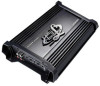
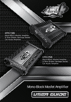
Mono-Block Mosfet Amplifier - Pyle HTG158 | Instruction Manual - Page 2
optimum performance, it is highly recommended that you read this Owners Manual before beginning installation. WARNING High powered audio systems in a vehicle 5 CONTROL FUNCTIONS 5 SPEAKER DIAGRAMS MONO CHANNEL 8 TROUBLESHOOTING GUIDE 9 WARNINGS 9 SPECIFICATION 10 2 www.Lanzar.com - Pyle HTG158 | Instruction Manual - Page 3
PLANNING YOUR SYSTEM Before beginning the installation, consider the following: 1. Do you plan to add additional mobile electronics equipment in the future? If you plan to expand your system by adding other components sometime in the future, ensure adequate space is left and cooling requirements are - Pyle HTG158 | Instruction Manual - Page 4
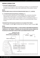
WIRING CONNECTION 1. Ground: To Vehicle Chassis To avoid unwanted ignition noise caused by ground loop, it is essential that the Ampli er be grounded to a clean, bare, metal surface of the vehicle's Chassis NOTE: GROUND WIRE SHOULD NOT BE EXTENDED MORE THAN 3 FT. (1 METER). 2. +12 Volt (Fused) - Pyle HTG158 | Instruction Manual - Page 5
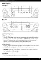
PANEL LAYOUT Front View Rear View CONTROL FUNCTIONS 1. RCA input jacks These RCA input jacks are for use with source units that have RCA or Line level outputs. A source unit with a minimum level of 200mV is required for proper operation. The use of high quality twisted pair cables is recommended to - Pyle HTG158 | Instruction Manual - Page 6
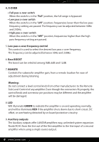
4. X-OVER • Full pass x-over switch When the switch is in the "Full" position, the full range is bypassed. • Low pass x-over switch When the switch is in the "LPF" position, frequencies lower than the low pass frequency setting are passed. The frequency can be adjusted between 50Hz and 250Hz. • High - Pyle HTG158 | Instruction Manual - Page 7
10. GND Connect this terminal directly to the sheet metal chassis of the vehicle, using the shortest wire necessary to make this connection. Always use wire of the same gauge or larger than the (+)12 volt power wire. The chassis connection point should be scraped free of paint and dirt. Use only - Pyle HTG158 | Instruction Manual - Page 8
System Diagrams MONO Channel System Design #1 HTG138 - HTG158 8 www.Lanzar.com - Pyle HTG158 | Instruction Manual - Page 9
TROUBLESHOOTING GUIDE WARNINGS Investigate the layout of your automobile thoroughly before drilling or cutting any holes. Take care when to work near the gas tanks, lines, or - Pyle HTG158 | Instruction Manual - Page 10
Speci cation HTG138 Features: • Class "AB" High-Current Dual Discrete Drive Stages • Mosfet PWM Power Supply • Electronic Crossover Network • Low Pass Filter Controls • Bass Boost Circuitry • Subsonic Circuitry • 2 Ohm Stable • Chrome RCA Inputs, Power Speaker Terminals • Line Output (L/R) Channels - Pyle HTG158 | Instruction Manual - Page 11
Speci cation HTG138 Features: • Class "AB" High-Current Dual Discrete Drive Stages • Mosfet PWM Power Supply • Electronic Crossover Network • Low Pass Filter Controls • Bass Boost Circuitry • Subsonic Circuitry • 2 Ohm Stable • Chrome RCA Inputs, Power Speaker Terminals • Line Output (L/R) Channels - Pyle HTG158 | Instruction Manual - Page 12
Questions? Issues? We are here to help! Phone: (1) 718-535-1800 Email: [email protected]
-
 1
1 -
 2
2 -
 3
3 -
 4
4 -
 5
5 -
 6
6 -
 7
7 -
8
-
9
-
10
-
11
-
12
 |
 |
Mono-Block Mosfet Amplifier