Pyle PCMT20 PCMT20 Manual 1
Pyle PCMT20 Manual
 |
View all Pyle PCMT20 manuals
Add to My Manuals
Save this manual to your list of manuals |
Pyle PCMT20 manual content summary:
- Pyle PCMT20 | PCMT20 Manual 1 - Page 1
PCMT20 PYLE® C;",D J @~:@F WWWPYLEAUDIO .COM - Pyle PCMT20 | PCMT20 Manual 1 - Page 2
OPERATING INSTRUCTION AC CLAMP METER Safety International Safety Symbols l.!.l ~ This symbol, adjacent to another symbol or terminal , indicates the user must refer to the manual for further information. IA. This symbol, adjacent to a terminal, indicates that, under normal use, hazardous i l l - Pyle PCMT20 | PCMT20 Manual 1 - Page 3
the button a second time to turn the backlight off. ZERO BUTTON For ACA and Capacitance Zero & Offset adjustment. Manual Ranging The meter turns on in the autoranging mode. Press the Range button to go to manual ranging. Each press of the range button will step to the next range as indicated by the - Pyle PCMT20 | PCMT20 Manual 1 - Page 4
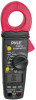
V AC, Frequency, Duty Cycle, 600V DC/AC Resistance, Diode, Continuity, Capacitance, Test 250V DC/AC Temperature CCtF) 60V DC/24V AC Meter Description 1. Current clamp 2. Clamp trigger 3. Rotary Function swith 4. LCD display 5. ZERO button 6. Data Hold and Backlight button 7. Mode select button - Pyle PCMT20 | PCMT20 Manual 1 - Page 5
5 pecif ications Function DC Current AC Current DC Voltage AC Voltage Resistance Capacitance Frequency Duty Cycle Temp (type-K) (probe accuracy not included) Range & Resolution 400.0~ 4000~ 400.0~ 4000~ 4 .000 AAC 40.00 AAC 400.0 AAC 400.0 mVDC 4.000 VDC 40.00 VDC 400.0 VDC 600 VDC 400.0 mVAC 4.000 - Pyle PCMT20 | PCMT20 Manual 1 - Page 6
NOTICES: Read and understand all warning and precaution statements listed in the safety section of this operation manual prior to using this meter. Set the function select switch to the OFF position when the meter is not in use. AC Current Measurements NO WARNING: Ensure that the test leads are
-
 1
1 -
 2
2 -
 3
3 -
 4
4 -
 5
5 -
 6
6
 |
 |

PCMT20
PYLE®
C;
",
D
J
@~
:
@
F
WWWPYLEAUDIO.COM