Pyle PCT40 Instruction Manual
Pyle PCT40 Manual
 |
View all Pyle PCT40 manuals
Add to My Manuals
Save this manual to your list of manuals |
Pyle PCT40 manual content summary:
- Pyle PCT40 | Instruction Manual - Page 1
end of the cable into the appropriate jack on the left side panel of the cable tester. Plug the other end of the cable into the appropriate jack connected to "l" on the left side plug. Use the charts below verify proper cable connections. If no LED lights than there is no connection and the left
-
 1
1
 |
 |

Enables quick convenient continuity cable
testing for all types of cables
LED's confirm each conductor continuity
and connection.
10 -way switch for selecting connections
to be tested. Also includes internal
battery and ground connection status
checks.
Rugged, compact, metal construction
for ultimate roadworthiness, long
life,
and reliability.
Tests cables with all types of combinations
of the following connectors:
* USB
* 3. 5mm Jacks
* 6. 35mm Jacks
* 3-PIN
XLR
* 5-PIN
XLR
* RCA/Phono
* 3-PIN DIN
* 5- PIN
DIN
* 8- PIN DIN
* 4-PIN S Type Jack
* RJ45
* 4-PIN SPEAKER
* 8 PIN SPEAKER
* 9V Alkaline Battery
Features:
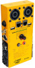
At first, turn the rotary switch fully clockwise to test the battery strength.
The battery LED will light bright green if the internal battery is fully
charged.
Then plug one one end of the cable into the appropriate jack on the left
side panel of the cable tester. Plug the other end of the cable into the
appropriate jack on the right side panel. Set the rotary switch to"l" to
test the connection of contact l on the plug inserted in to the left side
panel.
If there is a connection,
the Green LED willlight below "1" and a YELLOW
LED will light above each contact on the right side plug connected to "l"
on the left side plug. Use the charts below verify proper cable connections.
If no LED lights than there is no connection and the left side contact "1"
is "floating," due to design or an "open" in the cable.
Set the rotary switch to "2" to test contact 2, and so on, until all contacts
have been checked.
If the Ground LED lights than there is a connection between the
corresponding contacts and the chassis.
To test the cable with a banana plug, just plug each end of the cable
into the banana jacks: The LED will light and the unit will beep a tone
if there is connection between the plugs. These banana jacks can also
be used for continuity tests using two probe leads.
Cab/e testing:
Jack
Speakon
Phono
1 = sleeve
l =
-1
5 = -3
1
screen
2 =tip
2 = +1
6 = -3
2
=
hot
3 = ring
3 =
-2
7 = -4
4 = +2
8 =+4
1 Sleeve
Pin 1
2 Tip
Pin 2
3 Ring
Pin 3
1 Sleeve
1
Sleeve,
3
Ring
2 Tip
2
Tip
3 Ring
1
Sleeve,
3
Ring
1/4" TS
Mono to
1/4"
Mono
( Shorted
with
sleeve)
XLR
unbalanced
to
XLR unbalanced
Pin
1
Pin
1,
Pin
3
Pin
2
Pin 2
Pin
3
Pin 1,
Pin
3
1 Sleeve
1
Sleeve
2 Tip
2 Tip
3 Ring
3 Ring
1 Sleeve
Pin
1,
Pin
3
2 Tip
Pin
2
3 Ring
Pin
1,
Pin
3
(shorted
with sleeve)
1 / 4" TRS
to
1/4"
TRS
1/4"
TS
Mono
to
XLR
unbalanced
XLR
balanced
to
XLR balanced
1/4"
TRS
to
XLR
balanced
Pin
1
Pin 1
Pin
2
Pin 2
Pin
3
Pin 3