Pyle PDBT19 PDBT19 Manual 1
Pyle PDBT19 Manual
 |
View all Pyle PDBT19 manuals
Add to My Manuals
Save this manual to your list of manuals |
Pyle PDBT19 manual content summary:
- Pyle PDBT19 | PDBT19 Manual 1 - Page 1
is the radio out put (+) side. 3.It is recommended that you solder each connection for best results. 4.Secure condenser to speaker frame with glue. INSTRUCTIONS D' INSTALLATION Si vous achetez un Crossover Network pour votre haut-parleur woofer/medium/aigu vous n alrez pas besoin de connecter le
-
 1
1
 |
 |

TEMPLATE
E
E
ti
oti
06mm
tP0
49mm
),
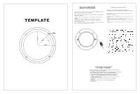
INSTALLATION
INSTRUCTIONS
FOR
MIDRANGE
OR
TWEETER
SPEAKERS
If
you
purchase
a
Crossover
Network
for
your
Woofer/Midrange/Tweeter
system
you
do
not
need
to
connect
condenser.
If
your
system
does
not
include
a
Crossover
Network,
you
must
connect
condenser
as
follows:
1.Connect
either
end
of
condenser
to
the
positive
terminal
(+)
of
speaker.
2.Connect
other
end
of
condenser
to
the
speaker
wire
harness,
Be
certain
to
connect
to
Positive
side
of
harness,
which
is
the
radio
out
put
(+)
side.
3.It
is
recommended
that
you
solder
each
connection
for
best
results.
4.Secure
condenser
to
speaker
frame
with
glue.
INSTRUCTIONS
D'
INSTALLATION
Si
vous
achetez
un
Crossover
Network
pour
votre
haut-parleur
woofer/medium/aigu
vous
n
alrez
pas
besoin
de
connecter
le
condensateur.
Si
votre
systeine
n
a
pas
un
Crossover
network
vous
devez
connecter
le
condensateur
comme
suit:
1
)Brancher
l'une
des
extremites
du
condensateur
a
la
borne
positive(+)
du
haut
parleur.
2)Brancher
l'autre
extrimite
du
condensateur
au
harnais
du
haut-parleur.
Assurez
vous
de
bien
connecter
le
cote
sortie
radio(+).
3)
II
est
recommande
de
souder
chaque
connections
pour
avoir
un
meilleur
resultat.
4)
II
est
plus
sex
del
fixer
le
condensateur
a
larmature
du
haut-parleur
avec
de
la
colle.
a
,)
Installation
lustination
for
midrange
or
Tweeter
Spankers
tL
trig
0)
-
7
7
-
(
Woofer
)
/
7
F1,
(
Midrange
)
—
—
(
Tweeter
)
F
-
(
Creasove
network)
6
'
:/
5
—
Condenser
)
<-
6&-t-
ti
45
4
")
I
ft;
1_,
7)
1,
,
tl,
f/A
-
)
---
1.
,
4:
-
.
1
7t
-
ii
-
4
,
F
7104,4>
,
-
-
-
+)
2.
D
—
0)t)
-
5
—is
-
Olt
(speaker)
(1)
7-1
i
(
wire
)
op
barness
)
ik
TT
°
—
.X
OD
l
i
#*
tr
°
-f
II
:>
°
A
-
(
Radio
)
0)
7
1,
1
'
7
°
7
f'
(Out
put)
op
P44
-
3.4*
-
i/r/L,
tt,
4-*
Lkt
-
tr/31)1,it
4.D
T
:/
4
)
-
-
Z
e
-t-
7
L
-
L
(
frame
)
:/rts
E
T'14,4-DTT
4
>
°
INSTRUCCIONES
DE
INSTALACION
DE
BOCINAS
0
TWEETERS
Si
usted
compra
un
crossover
para
sus
bafles
o
tweeters,
no
es
necesario
conectar
condensador.
Si
su
sistema
no
incluye
un
crossover,usted
tendria
que
conectar]
un
condensador
tal
y
como
se
describe
a
continuacion:
1-Conectar
cualquier
terminal
del
condensador
a
la
bocina.
2-Conectar
la
otra
terminal
del
condensador
a
la
bocina.
Asegurarse
de
conectar
el
positivo
del
cuadro,el
cual
es
la
salida
al
radio
lado
(+).
3
-Se
aconseja
soladr
cada
conexiOn
para
los
resultados
mejores.
4-Asegurar
el
condensador
en
el
marco
de
altavoz
con
kpegamento.