Pyle PDMT02 PDMT02 Manual 1
Pyle PDMT02 Manual
 |
View all Pyle PDMT02 manuals
Add to My Manuals
Save this manual to your list of manuals |
Pyle PDMT02 manual content summary:
- Pyle PDMT02 | PDMT02 Manual 1 - Page 1
INSTRUCTION MANUAL POCKET AUTORANGING DMM PDMT02 Safety International Safety Symbols This symbol, adjacent to another symbol or terminal, indicates the user must refer to the manual for further information. This symbol, adjacent to a terminal, indicates that, under normal use, hazardous voltages - Pyle PDMT02 | PDMT02 Manual 1 - Page 2
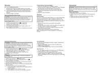
value. The displayed value is the difference between the reference value and the measured value. 1. Perform the measurement as described in the operating instructions. 2. Press the RELATIVE button to store the reading in the display and the "REL" indicator will appear on the display. 3. The display
-
 1
1 -
 2
2
 |
 |

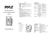
INSTRUCTION MANUAL
POCKET AUTORANGING DMM
PDMT02
www.pyleaudio.com
Safety
International Safety Symbols
This symbol, adjacent to another symbol or
terminal, indicates the user must refer to the manual
for further information.
This symbol, adjacent to a terminal, indicates that,
under normal use, hazardous voltages may be
present.
Double insulation
Safety Precautions
1.
Improper use of this meter can cause damage, shock, injury or
death. Read and understand this users manual before
operating the meter.
2.
Make sure any covers or battery doors are properly closed and
secured.
3.
Always disconnect the test leads from any voltage source
before replacing the battery or fuses.
4.
Do not exceed the maximum rated input limits.
5.
Use great care when making measurements if the voltages are
greater than 25VAC rms or 35VDC. These voltages are
considered a shock hazard.
6.
Always discharge capacitors and remove power from the
device under test before performing Capacitance, Diode,
Resistance or Continuity tests.
7.
Remove the battery from the meter if the meter is to be stored
for long periods.
Description
Meter Description
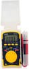
1.
3 3/4 Digit (4000 count)
2.
RELATIVE button
3.
SELECT button
4.
DATA HOLD button
5.
Hz/DUTY button
6.
Function switch
7.
Plastic case
8.
Test leads
Specifications
Electrical Specifications
Function
Range
Accuracy
400.0mV
(0.7% rdg + 3d)
4.000V, 40.00V,
(1.0% rdg + 3d)
DC Voltage
400.0V, 500V
(1.3% rdg + 3d)
4.000V, 40.00V
(1.0% rdg + 10d)
AC Voltage
40-60Hz
400.0V, 500V
(2.3% rdg + 5d)
400.0
4.000k
,
40.00k
, 400.0k
(2.0% rdg + 5d)
4.000M
(5.0% rdg + 5d)
Resistance
40.00M
(10.0% rdg + 5d)
4.000nF
40.00nF
(5.0% rdg + 30d)
400.0nF
(3.0% rdg + 15d)
Capacitance
4.000μF, 40.00μF,
200.0μF
(10.0% rdg + 15d)
Frequency
5.000Hz, 50.00Hz,
5000.0Hz, 5.000kHz,
50.00kHz, 500.0kHz,
10MHz
(2.0% rdg + 5d)
Duty Cycle
0.1-99%
Max input voltage
500V AC/DC
Input Sensitivity,
10Vrms min. <9.999KHz
(Frequency Ranges)
40Vrms min. >99.99KHz
Diode Test
Test current 1mA max., open circuit voltage
of 1.5V typical
Continuity Check
Audible signal if the resistance is < 60
Display
4000 count 3 ¾ digit LCD
Over range indication
LCD displays “OL”
Polarity
Minus (-) sign for negative polarity.
Low Battery Indication
“BAT” symbol indicates low battery
condition.
Battery
CR2032 3V Lithium
Operating Temperature
32
o
F to 104
o
F (0
o
C to 40
o
C)
Storage Temperature
14
o
F to 122
o
F (-10
o
C to 50
o
C)
Weight
1.7oz (50g)
Size
4.25x2.2x.5” (108x56x11.5mm)
Standard
IEC1010
CAT II
500V Pollution degree II,
CE Approved