Pyle PDMT05 PDMT05 Manual 1
Pyle PDMT05 Manual
 |
View all Pyle PDMT05 manuals
Add to My Manuals
Save this manual to your list of manuals |
Pyle PDMT05 manual content summary:
- Pyle PDMT05 | PDMT05 Manual 1 - Page 1
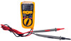
Instruction Manual 3in1 Pocket Autoranging DMM PDMT05 Auto Ranging DMM Hz% DT-118B OFF V A AU TO PO W ER OFF of this meter can cause damage, shock, injury or death. Read and understand this users manual before operating the meter. 2. Make sure any covers or battery doors are properly closed and - Pyle PDMT05 | PDMT05 Manual 1 - Page 2
Operation AC/DC VOLTAGE MEASUREMENTS CAUTION: Do not measure AC/ DC voltages if a motor on the circuit is being switched ON or OFF. Large voltage surges may occur that can damage the meter. 1. Set the function switch to the green V position. 2. Press the MODE button to indicate "DC" or "AC" on the
-
 1
1 -
 2
2
 |
 |

5
6
2
4
3
1
P
O
AU
O
T
OFF
E
R
W
OFF
A
V
R
a
n
A
u
t
o
D
M
M
i
n
g
g
8
9
7
10
DT-118B
T
O
AU
A
E
R
W
P
O
OFF
OFF
V
Hz%
R
a
n
Au
to
D
M
M
i
n
g
g
Instruction Manual
3in1 Pocket Autoranging DMM
PDMT05
Features
3-3/4 digit 4000 count) LCD display
Built-in non-contact AC voltage detector
plus flashlight
Double Molded housing
CATIII 1000V
200mA/500V Resettable Fused current inputs and
Overload protection on all ranges
Autoranging with auto power off
www.pyleaudio.com
Safety
International Safety Symbols
This symbol, adjacent to another symbol or
terminal, indicates the user must refer to the manual
for further information.
This symbol, adjacent to a terminal, indicates that,
under normal use, hazardous voltages may be
present.
Double insulation
Safety Precautions
1.
Improper use of this meter can cause damage, shock, injury or
death. Read and understand this users manual before
operating the meter.
2.
Make sure any covers or battery doors are properly closed and
secured.
3.
Always disconnect the test leads from any voltage source
before replacing the battery or fuses.
4.
Do not exceed the maximum rated input limits.
Input Limits
Function
Maximum Input
V DC or V AC
600V DC/AC
μA AC/DC
200mA/500V fast acting
Resettable Fuse
Resistance, Diode &
Continuity Test
600V DC/AC
5.
Use great care when making measurements if the voltages are
greater than 25VAC rms or 35VDC. These voltages are
considered a shock hazard.
6.
Always discharge capacitors and remove power from the
device under test before performing Diode, Resistance or
Continuity tests.
7.
Remove the battery from the meter if the meter is to be
stored for long periods.
Meter Description
1.
Non-contact AC voltage detector probe tip
2.
Non-contact AC voltage indicator light
3.
3 3/4 Digit (4000 count)
4.
MODE button
5.
Function switch
6.
Flashlight
7.
Flashlight button
8.
Hz/%Duty button
9.
Battery Cover
10.
Test leads
Specifications
Electrical Specifications
Function
Range
Accuracy
400mV,
(0.5% rdg + 3d)
DC Voltage
4.000V,40.00V, 400.0V,
600V
(1.2% rdg + 3d)
4.000V, 40.00V
(1.0% rdg + 8d)
AC Voltage
50-60Hz
400.0V, 600V
(2.3% rdg + 10d)
400.0
µ
A,
4000
µ
A
DC Current
40.00mA, 200.0mA
(2.0% rdg + 8d)
400.0
µ
A,
4000
µ
A
AC Current
50-60Hz
40.00mA, 200.0mA
(2.5% rdg + 10d)
400.0
(0.8% rdg + 5d)
4.000k
, 40.00k
,
400.0k
(1.2% rdg + 5d)
4.000M
(5.0% rdg + 5d)
Resistance
40.00M
(10.0% rdg + 5d)
4.000nF
(5.0% rdg + 0.6nF)
40.00nF
(5.0% rdg + 30d)
400.0nF
(3.0% rdg + 15d)
Capacitance
4.000μF, 40.00μF,
200.0μF
(5.0% rdg + 25d)
Frequency
9.999Hz, 99.999Hz,
999.9Hz, 9.999kHz,
(2.0% rdg + 5d)
Duty Cycle
0.5-99%
(2.0% rdg + 5d)
Max input voltage
600V AC/DC
Diode Test
Test current 1mA max., open circuit voltage
of 1.5V typical
Continuity Check
Audible signal if the resistance is <100
Display
4000 count 3 -3/4 digit LCD
Over range indication
LCD displays “OL”
Polarity
Minus (-) sign for negative polarity.
Low Battery Indication
“BAT” symbol indicates low battery
condition.
Input Impedance
>7.5M
Ω
(VDC & VAC)
AC Response
Average responding
ACV Bandwidth
50Hz to 60Hz
Auto Power Off
15 minutes (approximately)
Fuse
mA, μA ranges; 0.4A/600V
fast acting
Resettable Fuse
Batteries
Two 1.5V AAA
Operating Temperature
32
o
F to 104
o
F (0
o
C to 40
o
C)
Storage Temperature
14
o
F to 122
o
F (-10
o
C to 50
o
C)
Weight
145g
Size
104x55x32.5mm
Standard
IEC61010-1
CAT III
1000V Pollution
degree II, CE Approved