Pyle PDMT25 PDMT25 Manual 1
Pyle PDMT25 Manual
 |
View all Pyle PDMT25 manuals
Add to My Manuals
Save this manual to your list of manuals |
Pyle PDMT25 manual content summary:
- Pyle PDMT25 | PDMT25 Manual 1 - Page 1
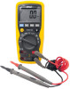
OPERATING INSTRUCTIONS AUTORANGING DIGITAL MULTIMETER PDMT25 ¡ Cã ¡ Fã Ω 10A V 10A A mA V www.pyleaudio.com 1 - Pyle PDMT25 | PDMT25 Manual 1 - Page 2
SAFETY WARNINGS The following safety information must be observed to insure maximum personal safety during the operation at this meter: Measurements beyond the maximum selected range must not be attempted. Extreme care must be taken when measuring above 50 V, especially on live bus-bars. To - Pyle PDMT25 | PDMT25 Manual 1 - Page 3
instrument are: Caution: refer to accompanying notes. This symbol indicates that the operator must refer to an explanation in the Operating Instructions to avoid personal injury or damage to the meter. Caution: risk of electric shock This WARNING symbol indicates a potentially hazardous situation - Pyle PDMT25 | PDMT25 Manual 1 - Page 4
MAX This CAUTION symbol indicates a potentially hazardous situation, which if not avoided, may result damage to the product. This symbol advises the user that the terminal(s) so marked must not be connected to a circuit point at which the voltage with respect to earth ground exceeds (in this case) - Pyle PDMT25 | PDMT25 Manual 1 - Page 5
SYMBOLS AND ANNUNCIATORS ))) Continuity BAT Low Battery Diode test HOLD Data Hold AUTO AutoRanging AC Alternating Current or Voltage DC Direct Current or Voltage MAX/MIN PEAK scope Stores the highest or lowest measurement Find glitches and transients without a V A, mA,uA Backlight - Pyle PDMT25 | PDMT25 Manual 1 - Page 6
OPERATION To turn on the instrument turn the range knob from the OFF position to any measurement range. Note: For best battery life ALWAYS turn the function switch to the OFF position when the meter is not in use. This meter has Auto OFF that automatically shuts the meter OFF if 30 minutes elapse - Pyle PDMT25 | PDMT25 Manual 1 - Page 7
measurement for later reference. 1. Press the HOLD button to "freeze" the reading on the indicator. The "HOLD" message will be appear in the display. 2. Press the HOLD button again to return to normal operation. BACKLIGHT button 1. Press the BACKLIGHT button to switch on the display light. 2. Press - Pyle PDMT25 | PDMT25 Manual 1 - Page 8
Peak Hold button The Peak Hold function captures the peak AC or DC voltage or current. The meter can capture negative or positive peaks as fast as 1 millisecond in duration. 1. Turn the function switch to the A or V position. 2. Use the MODE button to select AC or DC. 3. Allow time for the display - Pyle PDMT25 | PDMT25 Manual 1 - Page 9
for most measurements. For measurement situations requiring that a range be manually selected, perform the following: 1. Press the RANGE button. The "Auto Range" display indicator will turn off, The "Manual Range" display indicator will turn on 2. Press the RANGE button to step - Pyle PDMT25 | PDMT25 Manual 1 - Page 10
4. DC/DC VOLTAGE MEASUREMENT 1.sert the black test lead into the negative COM terminal and the red test lead into the positive V terminal. 2. Set the function switch to the VAC or VDC position. 3.Use the MODE button to select AC or DC Voltage 4.Connect the test leads in parallel to the circuit under - Pyle PDMT25 | PDMT25 Manual 1 - Page 11
test lead banana plug into the 10A jack. 5. Press the AC/DC button until "DC" appears in the display. 6. Remove power from the circuit under test, then open up the circuit at the point where you wish to measure current. 7. Touch the black test probe tip to the negative side of the circuit. Touch the - Pyle PDMT25 | PDMT25 Manual 1 - Page 12
AC CURRENT MEASUREMENT 1. Insert the black test lead plug into the negative (COM) socket. 2. For current measurements up to 10A, set the function switch to the A position and insert the red test lead plug into the (10A) jack. 3. For current measurements up to 400mA, set the function switch to the mA - Pyle PDMT25 | PDMT25 Manual 1 - Page 13
indicate the proper decimal point, value and symbol. RESISTANCE [ Ω ] MEASUREMENT WARNING: To avoid electric shock, disconnect power to the unit under test and discharge all capacitors before taking any resistance measurements. Remove the batteries and unplug the line cords. 1. Set the function - Pyle PDMT25 | PDMT25 Manual 1 - Page 14
CONTINUITY CHECK WARNING: To avoid electric shock, never measure continuity on circuits or wires that have voltage on them. 1. Set the range switch to the ))) position. 2. Insert the black lead plug into the COM socket and the red test lead plug into the positive ))) socket. 3. Press the MODE - Pyle PDMT25 | PDMT25 Manual 1 - Page 15
DIODE TEST WARNING: To avoid electric shock, do not test any diode that has voltage on it. 1. Set the function switch to the position. 2. Insert the black test lead plug into the COM socket and the red test lead plug into the socket. 3. Press the MODE button until " display. " appears in the - Pyle PDMT25 | PDMT25 Manual 1 - Page 16
CAPACITANCE MEASUREMENT WARNING: To avoid electric shock, discharge the capacitor under test before measuring. 1.Set the function switch to the CAP capacitance position. 2. Insert the black test lead banana plug into the negative COM jack and the red test lead banana plug into the CAP positive jack. - Pyle PDMT25 | PDMT25 Manual 1 - Page 17
plug into the positive Hz jack. 3. Touch the test probe tips to the circuit under test. 5. Read the frequency in the display. The digital reading will indicate the proper decimal point, symbols (kHz, MHz) and value. TEMPERATURE MEASUREMENT 1.Set the function switch to the Type K ºF or ºC position - Pyle PDMT25 | PDMT25 Manual 1 - Page 18
5.Read the temperature in the display. Note: The temperature probe is fitted with a type K mini connector. A mini connector to banana connector adaptor is supplied for connection to the input banana jacks. 18 - Pyle PDMT25 | PDMT25 Manual 1 - Page 19
at the distribution level; CAT IV meters are designed to protect against transients from the primary supply level (overhead or underground utility service). Maximun voltage between any terminal and earth ground: 1000V DC/AC RMS Surge Protection: 8kV peak IEC 61010 Display: 4000 counts LCD - Pyle PDMT25 | PDMT25 Manual 1 - Page 20
Measurement rate: 2 times per second nominal. Auto power off: Meter automatically shuts down after approx. 30 minutes of inactivity. Operating environment: -10 oC to 50 oC (14 oF to 122 oF) at < 70 % relative humidity. Storage temperature: -30 oC to 60 oC (-4 oF to 140 oF) at < 80 % relative - Pyle PDMT25 | PDMT25 Manual 1 - Page 21
dc or 1000V ac rms. AC Voltage (Auto-ranging) Range Resolution Accuracy 400.0mV 0.1mV 4.000V 1mV +0.8%of rdg + 3 digits 40.00V 10mV 400.0V 100mV 1000V 1V +1.2%of rdg + 5 digits Input Impedance: 7.8MΩ. AC Response: 50 Hz 60Hz Maximum Input: 1000V dc or 1000V ac rms. DC Current (Auto - Pyle PDMT25 | PDMT25 Manual 1 - Page 22
dc on 10A range. AC Current (Auto-ranging) Range Resolution Accuracy 400.0uA 0.1uA 4000uA 1uA +1.5% of rdg + 5 digits 40.00mA 10uA 400.0mA 100uA 10A 10mA +3.0% of rdg + 5 digits Overload Protection: 0.5A / 1000V and 10A / 1000V Fuse. AC Response: 50 Hz to 60 Hz Maximum Input: 400uA ac - Pyle PDMT25 | PDMT25 Manual 1 - Page 23
Resistance [Ω] (Auto-ranging) Range Resolution Accuracy 400.0Ω 0.1Ω +0.8% of rdg + 5 digits 4.000kΩ 1Ω 40.00kΩ 10Ω +0.8% of rdg + 2 digits 400.0kΩ 100Ω 4.000MΩ 1kΩ +2.5% of rdg +8digits 40.00MΩ 10kΩ Input Protection: 1000V dc or 1000V ac rms. Capacitance (Auto-ranging) Range - Pyle PDMT25 | PDMT25 Manual 1 - Page 24
rdg +8dgts Sensor: Type K Thermocouple Overload protection: 1000V dc or ac rms.. Diode Test Test current Resolution Accuracy 1Ma 1 mV +10% of rdg + 5 typical/Open digits MAX.3V Open circuit voltage: MAX. 3V dc 24 - Pyle PDMT25 | PDMT25 Manual 1 - Page 25
batteries become exhausted or drop below the operating voltage, the battery warning symbol will appear in the LCD display. The battery should be replaced. 2. Follow instructions for installing battery. See the Battery Installation section of this manual. 3. Dispose of the old battery properly. 25 - Pyle PDMT25 | PDMT25 Manual 1 - Page 26
WARNING: To avoid electric shock, do not operate your meter with the battery cover removed. BATTERY INSTALLATION WARNING: To avoid electric shock, disconnect the test leads from any source of voltage before removing the battery cover. Do not operate the instrument with the battery cover removed 1. - Pyle PDMT25 | PDMT25 Manual 1 - Page 27
REPLACING THE FUSES WARNING: To avoid electric shock, disconnect the test leads from any source of voltage before removing the fuse /battery cover. 1. Disconnect the test leads from the meter and any item under test. 2. Open the fuse door by loosening the screw on the door using a Phillips head
-
 1
1 -
 2
2 -
 3
3 -
 4
4 -
 5
5 -
 6
6 -
 7
7 -
8
-
9
-
10
-
11
-
12
-
13
-
14
-
15
-
16
-
17
-
18
-
19
-
20
-
21
-
22
-
23
-
24
-
25
-
26
-
27
 |
 |

1
V
mA
A
10A
¦¸
V
Ω
10A
¡ã
C
F
¡ã
¡ã ¡ã
OPERATING INSTRUCTIONS
AUTORANGING DIGITAL MULTIMETER
PDMT25
www.pyleaudio.com