RCA RT2390 User Manual
RCA RT2390 - Home Theater Dolby ProLogic II Manual
 |
UPC - 044319402575
View all RCA RT2390 manuals
Add to My Manuals
Save this manual to your list of manuals |
RCA RT2390 manual content summary:
- RCA RT2390 | User Manual - Page 1
format. • Dolby Pro Logic II audio output format. FM / AM • Radio band indicator in Tuner mode. ST • Tuner stereo signal detected. OPT12 • Optical digital input detected. COAX • Coaxial digital input detected. user manual RT2390 It is important to read this instruction book prior to using your - RCA RT2390 | User Manual - Page 2
Night mode is available only with Dolby Digital playback. Advanced Sound Control Dynamic Bass Amplified System (dBas) With "Dynamic Bass Amplified System" (dBas), the discrete amplifier is located in the receiver so the subwoofer keeps the power needed to reproduce powerful effects. 4 settings
-
 1
1 -
 2
2
 |
 |
7.
Adjustment Buttons
• Press the Left or Right buttons to select
among setting items in setup mode: SLEEP,
DIMMER, SPEAKER DISTANCE, SPEAKER
SETUP, and audio input source (ANALOG,
OPTICAL / COAXIAL).
• Press the Up or Down buttons to adjust the
values when the display shows the setup you
want to change.
8.
SURROUND
Selects among surround sound settings: DOLBY
PL II EMULATION, DOLBY PL II MUSIC, DOLBY
PL II MOVIE, STEREO, DISCO, STADIUM,
THEATER, JAZZ CLUB, ARENA, 3 STEREO.
9. EQUALIZER
Selects among preset equalizer modes.
(only available in stereo mode)
10. NIGHT
Selects among Night mode options (DRC OFF,
SOFT and ON) which compresses the volume
difference between normal voices and sounds
such as explosions. (Available only during
Dolby digital signal playback)
11. LEVEL
Speaker LEVEL setting and Test tone. Refer to
“Advanced Sound Control” for details.
12. SUBWOOFER
Selects among subwoofer output level (SOFT
SUBWOOFER, BALANCED SUBWOOFER,
STRONG SUBWOOFER, POWERFUL
SUBWOOFER).
13.
Number Buttons
Directly access a preset station in Tuner mode.
14. SETUP
Enters Setup mode. Use the Left and Right
adjustment buttons to select among setup
options. (SLEEP, DIMMER, FRONT SPK
DISTANCE, CENTER SPK DISTANCE, SURROUND
SPK DISTANCE, CENTER SPK ON/OFF,
SURROUND SPK ON/OFF, DIGITAL INPUT).
15.
Operation Buttons
In TUNER mode:
• Press the TUNER - and TUNER + keys to tune
down or up the radio frequency.
• Press SAVE to activate the preset station
saving and press to confirm preset station
settings.
• PLAY, RECORD, STOP and PAUSE keys are only
for easy control of external devices that are
connected to your receiver such as CD, VCR,
DVD, TAPE, etc.. The remote control currently
operates most Thomson, RCA and GE products.
Display
DVD / VCR / SAT / TUNER / TAPE / CD / TV
•
An arrow points to the current source mode.
•
Dolby Digital audio input for signal
format.
•
Dolby Pro Logic II audio output
format.
FM / AM
• Radio band indicator in Tuner mode.
ST
•
Tuner stereo signal detected.
OPT12
•
Optical digital input detected.
COAX
• Coaxial digital input detected.
TUNED
•
Tuner station detected.
•
Speaker Icons.
L - Front left speaker
C - Center speaker
R - Front right speaker
LS - Left surround (rear) speaker
RS - Right surround (rear) speaker
LFE - Subwoofer speaker
SLEEP
•
Unit in Sleep mode.
MEMORY
•
Unit is in Tuner Preset Station mode.
KHz / MHz
• Tuner frequency unit.
Switching the unit on and off
•
To switch on the receiver, press the
STANDBY/ON
button on the main unit once,
or the
ON•OFF
button on the remote
control.
•
Standby: when the receiver is in tuner
mode, press the
STANDBY/ON
button once
to enter standby mode.
On the remote control, press the
ON•OFF
button twice within 2 seconds if the receiver
is not in Tuner source mode to enter standby
mode.
To avoid entering standby mode when
powering up the unit, do not press the
ON•OFF
button twice within 2 seconds.
•
The receiver draws a small amount of
electricity when in standby mode.
Unplugging the unit from the wall
socket will stop the draw.
Selection of source
When one of the source button is pressed, the
input corresponding to the name will be
activated.
The receiver acts as a switching device between
all the sources that are plugged into it.
user
manual
EXPORTER
Thomson Inc.
P.O. Box 1976
Indianapolis, IN 46206 - 1976
© 2004 Thomson Inc.
Trademark(s) ® Registered
Marca(s)
Registrada(s)
Marque(s)
Deposée
55984640 (EN)
www.rca.com
Printed in China / Impreso en China
IMPORTADOR
Comercializadora Thomson de México,
S.A. de C.V.
Álvaro Obregón No. 151. Piso 13.
Col. Roma. Delegación Cuauhtémoc
C.P. 06700. México, D.F.
Telefono: 52-55-11-020360
RFC: CTM-980723-KS5
RT2390
It is important to read this instruction book prior to using your new product for the first time.
Es importante leer este manual antes de usar por vez primera su euipo.
This device complies with Part 15 of the FCC
Rules. Operation is subject to the following two
conditions: (1) This device may not cause
harmful interference, and (2) this device must
accept any interference received, including
interference that may cause undesired
operation.
In accordance with FCC requirements, changes
or modifications not expressly approved by
Thomson Inc. could void the user’s authority to
operate this product.
This device generates and uses radio frequency
(RF) energy, and if not installed and used
properly, this equipment may cause
interference to radio and television reception.
If this equipment does cause interference to
radio or television reception (which you can
determine by unplugging the unit), try to
correct the interference by one or more of the
following measures:
•
Re-orient the receiving antenna (that is, the
antenna for the radio or television that is
"receiving" the interference).
•
Move the unit away from the equipment
that is receiving interference.
•
Plug the unit into a different wall outlet so
that the unit and the equipment receiving
interference are on different branch circuits.
If these measures do not eliminate the
interference, please consult your dealer or an
experienced radio/television technician for
additional suggestions.
Also, the Federal Communications Commission
has prepared a helpful booklet, "How To
Identify and Resolve Radio TV Interference
Problems." This booklet is available from the
U.S.
Government Printing Office, Washington, DC
20402. Please specify stock number 004-000-
00345-4 when ordering copies.
This product complies with DHHS Rules 21 CFR
Subchapter J. Applicable at the date of
manufacture.
Technical Specification
Product: Dolby Digital Audio Receiver
Brand: RCA
Model: RT2390
Electrical current consumption
Power Supply: 120V ~ 60Hz
Power consumption: 135 Watts
IMPORTER
Comercializadora Thomson de México, S.A. de
C.V.
Álvaro Obregón No. 151. Piso 13.
Col. Roma. Delegación Cuauhtémoc
C.P. 06700. México, D.F.
Telefono: 52-55-11-020360
RFC: CTM-980723-KS5
For Your Safety
The AC power plug is
polarized (one blade is wider
than the other) and only fits
into AC power outlets one
way. If the plug won’t go into
the outlet completely, turn
the plug over and try to insert
it the other way. If it still won’t fit, contact a
qualified electrician to change the outlet, or
use a different one. Do not attempt to bypass
this safety feature.
CAUTION: TO PREVENT ELECTRIC SHOCK,
MATCH WIDE BLADE OF PLUG TO WIDE
SLOT, FULLY INSERT.
For Your Records
In the event that service should be required,
you may need both the model number and the
serial number.
In the space below, record the
date and place of purchase, and the serial
number:
Model No.
Remote Control No.
Date of Purchase
Place of Purchase
Serial No.
Service Information
This product should be serviced only by those
specially trained in appropriate servicing
techniques. For instructions on how to obtain
service, refer to the warranty included in this
Guide
FCC Information
WARNING:
TO PREVENT FIRE OR ELECTRICAL
SHOCK HAZARD, DO NOT EXPOSE THIS PRODUCT
TO RAIN OR MOISTURE.
SEE MARKING ON BOTTOM / BACK OF PRODUCT
CAUTION
RISK OF ELECTRIC SHOCK
DO NOT OPEN
THE EXCLAMATION
POINT WITHIN THE
TRIANGLE IS A
WARNING
SIGN
ALERTING YOU
OF
I M P O R TA N T
INSTRUCTIONS
ACCOMPANYING
THE
P R O D U C T.
THE
LIGHTNING
FLASH AND ARROW-
HEAD WITHIN THE
TRIANGLE
IS
A
WARNING
SIGN
ALERTING YOU OF
"DANGEROUS
VOLTAGE" INSIDE
THE PRODUCT.
CAUTION: TO REDUCE THE
RISK OF ELECTRIC SHOCK,
DO NOT REMOVE COVER
(OR BACK). NO USER-
SERVICEABLE PARTS IN-
SIDE. REFER SERVICING
TO QUALIFIED SERVICE
PERSONNEL.
Unpacking the Receiver
You should recive the following items:
• One receiver unit
• One pair of “AAA” batteries
• One pig-tail antenna wire
•
One external AM loop antenna
•
One instruction book;
•
One safety leaflet
•
One Quick Connection Guide
•
One Remote Control
Unpacking The Speakers
One set of speakers including:
• 1 set of left and right front speakers,
• 1 centre speaker,
• 1 subwoofer and
•
1 set of left and right rear speakers
• 6 speaker wires including:
- 1 X green/grey striped wire for
center speaker
- 1 X red/grey striped wire for front
right speaker
- 1 X white/grey striped wire for front
left speaker
- 1 X purple/grey striped wire for
subwoofer
- 1 X blue/grey striped wire for rear
left speaker
- 1 X gray/grey striped wire for rear
right speaker
Inserting Batteries into Remote
Control
Insert two “AAA” (R03) batteries according to
the + and - signs in the battery compartment.
To use the remote control, point it directly at
your receiver.
Install batteries as follows:
1. Remove battery compartment door by
applying thumb pressure on battery door and
then lift the door out and off the cabinet.
2. Insert 2 AAA batteries in the compartment
and replace the compartment door.
Set up and Maintenance of the
Receiver
Provide spaces for sufficient ventilation as
indicated:
• Do not connect to the AC power cords until
all connections are completed.
• Do not use your set immediately after
transferring it from a cold place to a warm
place: there is risk of condensation.
• Do not expose your set to water and
excessively high temperatures.
•
After having disconnected your set, clean the
case with a soft cloth, or with a slightly damp
leather chamois. Never use strong solvents.
Protect your Components from
Overheating
• Do not block ventilation holes in any
component. Arrange the components so that
air can circulate freely.
• Do not stack components directly on top of
each other.
• Do not place the unit near other components
that generate heat such as heating vents.
•
Allow adequate ventilation when placing
your components in a stand.
•
Place an amplifier near the top shelf of the
stand so heated air rising from it will not
affect other components. If you have a
satellite receiver, you should place it on the
top shelf.
10 cm/4"
5 cm/
2"
10 cm/4"
10 cm/
4"
10 cm/
4"
Front View
Side View
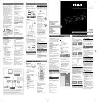
Connecting to Audio Components
AUDIO INPUT
DVD
SAT
TV
VCR
CD
TAPE
DIGITAL AUDIO
COAXIAL
OPTICAL
L
R
IN
TV
VCR
CD Player
SAT
to LINE OUT (Tape Deck)
to AUDIO OUT
(CD)
to AUDIO OUT (SAT)
to AUDIO OUT
(DVD)
to AUDIO OUT (TV)
to AUDIO OUT (VCR)
Tape Deck
DIGITAL INPUT
Connect components capable of
outputing Dolby Digital (e.g. DVD or
SAT) or standard PCM (CD) format
digital signals. Read section on
"Input Signal Setting" under
"Advanced Sound Control" carefully
to adjust the matching input
settings.
If your CD player is equipped with digital optical
jacks, use of optical cable is preferred. What you
need is just one more optical digital connecting
cable
(not supplied). Plug it in the digital input jack
of the receiver and select OPTICAL on the receiver
setting (see details under "Input Signal Setting").
You can enjoy better sound quality brought to you by
the optical cable. When optical cable is used, analog
cables are still needed for recording to tape output.
DVD
DIGITAL CONNECTION
If you have a SAT receiver DVD player or CD player with a digital output, you can make use of an optical digital cable (not
supplied) or coaxial digital cable (not supplied) to carry the audio portion of the signal and enjoy Dolby Digital sound quality.
One optical or coaxial cable is needed for each SAT receiver, DVD player or CD player. When optical or coaxial cable is used,
the analog audio cables are still needed if recording through a tape or VCR is desired. This receiver provides one optical and
one coaxial digital input for the connection of your components. Please connect your components (e.g. DVD, SAT or CD) to the
appropriate digital inputs and press DIGITAL INPUT to select the corresponding digital input source.
Note: Optical and coax cables carry only the audio portion of the signal. A video connection must also be established for a SAT
receiver and DVD player.
Digital Connections
Read instructions carefully when
connecting components to the receiver.
Digital In Jacks can accept Dolby Digital (AC-3)
or PCM signals when compatible components
are connected.
TV Connections
TVs with RF input may need a RF modulator
(not included) for inputting audio signals.
Connecting the Antennas
The AM and FM antennas connect to the AM
and FM terminals on the system’s back panel.
They must be hooked up in order to receive
clear reception.
AM Loop Antenna and FM Indoor
Antenna
1. Uncoil the Antenna wire and locate the base
end of the AM antenna.
2. Press down on the Antenna tab to open the
terminal.
3. Inert the antenna wires into the terminal
and release the tabs to secure the wires in
place.
Connecting for Power
Make sure you connect all
your other electronic
components and the speakers
before plugging your receiver
into the outlet. Plug the
power cord in the wall outlet,
matching the wide blade of
the plug with the wide slot in the outlet. Be
sure to insert the plug completely.
Using Headphones
To listen privately through
your audio system, use the
PHONES jack on the receiver.
However, make sure you turn
down the volume before you
put on the headphones.
Increase the volume to the
desired level after
headphones are in place.
Once headphones are connected,
“HEADPHONE DOWN MIX 2 CHANNEL” will
scroll on display. This feature automatically
converts multi-channel speaker outputs to 2
channel stereo for your listening pleasure.
Hearing Comfort & Well-Being
• Do not play your headset at a high volume.
Hearing experts advise against continuous
extended play.
•
If you experience a ringing in your ears,
reduce volume or discontinue use.
Factory Setting
The unit is preset to the following settings
when you first power the receiver up right out
of the box:
Function = TUNER
Volume setting = 25
Bass & treble = 0 dB
EQ - FLAT
Speaker settings: Center, surr = YES
Subwoofer = STRONG
DRC = OFF
Reset to Factory Settings
You may restore factory setting with the
following procedures:
1. Enter SAT mode.
2. Press
PRESET UP
,
PRESET DOWN
,
SOURCE
UP
to reset the unit.
All preset stations will reset to FM87.5MHz and
all receiver settings restore to default settings
as described above.
FM 75‰
3‰
FR
FL
SR
SL
CEN
SUB
6‰
SPEAKERS
DIGITAL AUDIO
COAXIAL
OPTICAL
GND
AM LOOP
SAT / DVD / CD Player / TV
COAXIAL DIGITAL IN (AUDIO)
Connect to coaxial digital output of
DVD, CD, SAT or other compatible
devices.
OPTICAL DIGITAL IN (AUDIO)
Optical Fiber Cable
Connect to optical digital output of
DVD, CD, SAT or other compatible
devices.
DVD / CD / SAT
DIGITAL AUDIO
COAXIAL
OPTICAL
AUDIO INPUT
DVD
SAT
TV
VCR
CD
TAPE
L
R
IN
SUBWOOFER
AUDIO OUT
RF modulator
TV
RF cable
Audio cable
The diagram shown above may varies from your actual RF
modulator, please refer to your RF modulator manual.
Audio in
Audio out
RF in
RF out
HINT
•
For FM reception, extend antenna to its
full length.
•
For AM reception, rotate the antenna
horizontally to get better reception.
Getting Started
Getting Started
Dolby and the double-D symbol are
registered trademarks of Dolby
Laboratories.
NOTE
STRONG SUBWOOFER setting makes the
output level of subwoofer speaker to be
stronger than normal Dolby setting. Adjust
the SUBWOOFER setting by pressing the
SUBWOOFER key to achieve the best bass
performance.
WARNING
All preset radio stations and surround
sound setting will be lost after factory
setting is restored.
Operating Your Receiver
NOTE
The remote control button
CLEAR, MENU
and GUIDE do not function for this receiver
but can be used to control other RCA and
Thomson products.
S
RS
R
C
LS
RS
LFE
R
C
L
Example 1:
If you have connected a DVD player to the DVD
input
on the receiver, press the
SOURCE
buttons on the main unit repeatedly until DVD
is selected or press
DVD•6CH
on the remote
control to receive the sounds and images
transmitted by the DVD.
Example 2:
Based on the example 1, the DVD is playing , if
a VCR is connected
to the VCR input of the
receiver, press the
SOURCE
buttons on the
main unit repeatedly until VCR is selected or
press
AUX 1 (VCR)
on the remote control. The
sound from the VCR source will replace the
DVD.
You can connect up to 6 audio sources to this
amplifier:
Source button
Corresponding connector
(receiver front panel)
(receiver back panel)
- DVD
DVD IN
- SAT
SAT IN
- TV
TV IN
- VCR
VCR IN
- CD
CD IN
- TAPE
TAPE IN
- FM/AM
built-in
An arrow points to the source name selected
shown on the display.
Example:
Press
DVD
to select DVD as the
source to the amplifier.
Using the Remote to Control
Additional Components
You can use your remote to control most of
RCA branded VCRs, satellites, cable boxes or
TVs.
Press the corresponding source button on the
remote control to operate options on other
components.
Volume Punchthrough
By default, the
VOL+
/
VOL-
and
MUTE
buttons
will only control the receiver, regardless which
mode (TV, VCR, etc) the receiver is in.
By programming the volume punchthrough
function, you can also control the volume of
the TV.
To activate the volume punchthrough function,
follow the procedures below:
1. Press and hold the
VOL-
button.
2. While holding down the
VOL-
button, press
one of the source buttons to select the
source where you want to control TV volume
at. (
DVD
,
TV
,
VCR
or
SAT•CABLE
)
3. Continue holding down the
VOL-
button and
press the
TV
button once.
4. Release all buttons.
You should now be able to control TV volume
and mute at the selected device.
Using the receiver to play a source
After having properly connected a source (DVD,
CD, VCR) to the receiver, you can partly control
them through the receiver.
Playing a DVD with the receiver
1. Connect a DVD player to the receiver (see
connecting your receiver for details).
2. Press
ON/STANDBY
on the main unit or press
ON•OFF
on the remote control to switch on
the receiver.
3. Press the
SOURCE
buttons on the main unit
or
DVD•6 CH
on the remote control to select
the DVD source.
4. Switch ON the DVD player and start
playback.
5. Switch ON your TV.
6. Select the appropriate A/V channel on the TV
(refer to your TV manual for details) until the
image from the DVD player is displayed.
7. Set the sound Mode if needed (see
"Advanced sound control" for details).
Example 1:
To play Dolby Prologic II Movie sound, press
the
SURROUND
buttons until "Dolby PL II
MOVIE" appears on the Display and all of the
speaker'’ icons light up.
Example 2:
LD:
You may need to select a different Audio
Channel on your LD (refer to your LD player
manual).
8. Adjust the volume knob accordingly.
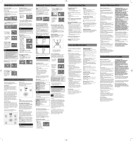
Receiver Controls
1. ON/STANDBY
Turns the unit on and off. When the
system is turned on, the unit will go to the
mode it was in before powered off.
2. Display
Displays current status of the receiver.
3. SUBWOOFER
Selects among subwoofer sound level.
(SOFT SUBWOOFER, BALANCED SUBWOOFER,
STRONG SUBWOOFER, POWERFUL
SUBWOOFER)
4. SOURCE Buttons
Selects sound source. (DVD, Tuner, Tape, VCR,
CD, TV and SAT)
5. SURROUND Buttons
Selects digital sound processor.
(DOLBY PL II MOVIE, STEREO, DISCO,
STADIUM, THEATER, JAZZ CLUB,
ARENA, 3 STEREO, DOLBY PL
EMULATION, DOLBY PL II MUSIC)
6. PRESET Buttons
Selects preset station in Tuner mode.
7. VOLUME
Increases and decreases volume level
8. PHONES
Plug your headphones (not supplied)
into it
for your private enjoyment.
Speakers will be off when phones
are inserted.
Remote Control
Please be sure you have inserted the batteries
into the remote control. You can test it by
pressing any button.
1. ON•OFF
Turns the receiver and other auxiliary
components on and off. (see “Using the
Remote to Control Additional Components”).
2. Source Buttons
Selects various audio sources.
3. VOL + / VOL -(Volume Buttons)
Adjusts the volume level.
4. CH+ / CH- (Channel Buttons)
Selects programmed stations in TUNER mode.
5. MUTE
Mutes all audio output.
6. GO BACK / ST•MONO
•
Selects between Stereo and Mono sound in
Tuner mode.
1
2
3
4
5
6
7
8
2
1
3
5
4
6
7
8
9
10
11
12
13
14
15
2
Operating Your Receiver
Operating Your Receiver
NOTE
1. Your receiver has a built in tuner. Just
connect the appropriate antenna to the
back of the receiver and you will be
able to listen to radio stations. (See
details in Tuner section)
2. Other sources can be connected to the
above standard source. Example: you can
connect a LD into the DVD inputs.
3. Refer to the "Connecting To Audio
Components" section for details on
connection.
NOTE
The remote control can only operate RCA
brand products.
NOTE
Volume punchthrough can be done in all
non-Tuner modes.
NOTE
Controlling the TV volume can be done in
any non-Tuner modes.
HINT
To return to controlling receiver volume
and mute again, follow the steps above but
press TUNER instead of TV in step 3.
HINT
If batteries are removed from the battery
compartment of the remote control, the
volume and mute control in all source
modes will be the receiver volume and
mute conrol except in TV mode.
NOTE
To play Dolby Digital sound, the source
must be connected to the receiver via the
optical or coaxial terminal
NOTE
The system is equipped with Dolby Digital,
and manufactured under License from
Dolby Laboratories.
RT2390 EN sheet final
12/28/04
9:42 AM
Page 1