Radio Shack 15-1245 Owner's Manual
Radio Shack 15-1245 - Outdoor Antenna Rotator Manual
 |
UPC - 040293636807
View all Radio Shack 15-1245 manuals
Add to My Manuals
Save this manual to your list of manuals |
Radio Shack 15-1245 manual content summary:
- Radio Shack 15-1245 | Owner's Manual - Page 1
-In Wire Ground Clamp Electric Service Equipment Antenna Discharge Unit (NEC Section 810-20) Grounding Conductors (NEC Section 810-21) Grounding Clamps NEC - National Electrical Code Power Service Grounding Electrode System (NEC Article 250, Part H) 3. Your control is provided with ventilation - Radio Shack 15-1245 | Owner's Manual - Page 2
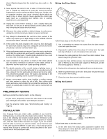
the Drive Motor" and "Wiring the Control"). • Test the antenna rotator (see "Synchronizing and Testing" on Page 3). INSTALLATION Use 20-gauge three-wire rotator cable, available at your local RadioShack store, to connect the drive motor to the control. The instructions in the following two sections - Radio Shack 15-1245 | Owner's Manual - Page 3
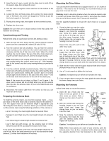
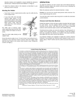
's dial to N, take the antenna rotator to your local RadioShack store for assistance. 4. Disconnect the rotator cable from the control so that you can mount the drive motor. Preparing the Antenna Mast To install the antenna rotator, you need two separate masts - a support mast for the drive motor - Radio Shack 15-1245 | Owner's Manual - Page 4
to the support mast. Loop in Antenna Cable Stand-Off Insulators Drive Motor Rotator Cable Taped to Mast Route the antenna cable to your TV and connect it according to the instructions in your antenna's owner's manual. Route the rotator cable from the drive motor to the control, then connect
-
 1
1 -
 2
2 -
 3
3 -
 4
4
 |
 |

©
2002 RadioShack Corporation.
All Rights Reserved.
RadioShack and RadioShack.com are trademarks used by RadioShack Corporation.
OWNER’S MANUAL — Please read before using this equipment.
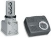
Antenna Rotator
Your RadioShack Antenna Rotator lets you turn and accurately posi-
tion even the largest TV antenna from inside your home to ensure the
best possible TV reception. When you turn the control’s dial to select a
direction, the drive motor turns the antenna. When the antenna reach-
es the desired direction, the motor automatically turns off.
Important:
For your safety, read “Important Safety Instructions” and
all safety, installation, and operating instructions supplied with your an-
tenna. Keep this manual for future reference.
IMPORTANT SAFETY INSTRUCTIONS
Your antenna rotator, consisting of a control and a drive, has been en-
gineered and manufactured to assure your personal safety. Improper
installation or abuse of the rotator, or the antenna connected to it, can
result in potential electrical shock hazards. In order not to defeat the
safeguards incorporated into the rotator, observe the following basic
rules for its installation, use, and servicing.
1. An outside antenna system should not be located in the vicinity of
overhead power lines or other electric light or power circuits, or
where it can fall into such power lines or circuits. When installing
an outside antenna system, extreme care should be taken to keep
from touching such power lines or circuits, as contact with them
might be fatal.
2. If the drive unit is installed on an outdoor antenna, be sure the
antenna system is grounded so as to provide some protection
against voltage surges and built-up static charges. Section 810 of
the National Electrical Code, ANSI/NFPA70, provides information
with respect to proper grounding of the mast and supporting struc-
ture, grounding of the antenna lead-in wire and drive unit to con-
trol unit interconnecting cables to an antenna discharge unit, size
of grounding conductors, location of antenna discharge unit, con-
nection to grounding electrodes, and requirements for the ground-
ing electrode.
3. Your control is provided with ventilation openings to allow heat
generated during operation to be released. If these openings are
blocked, heat build-up can cause failure of the control and exter-
nal damage. Therefore:
•
Never block the ventilation slots by placing the control on a soft
surface, such as a bed, sofa, or rug.
•
Never place the control in a built-in enclosure unless proper
ventilation is provided.
•
Never cover the control’s openings with cloth or other material.
•
Never place the control near or over radiators, heat registers,
amplifiers, or other heat sources.
4. Your control might be equipped with a polarized AC line plug (one
blade of the plug is wider than the other). This safety feature
allows the plug to fit into the power outlet only one way. Should
you be unable to insert the plug fully into the outlet, try reversing
the plug. Should it still fail to fit, contact your electrician to replace
the obsolete outlet. Do not defeat the safety purpose of the polar-
ized plug.
5. Operate the control only from an AC power source as indicated on
the bottom of the control. Do not use DC.
6. Overloaded AC outlets and extension cords are dangerous, and
so are frayed power cords and broken plugs. They may result in a
shock or fire hazard. Unplug the control and call your service tech-
nician for replacement.
7. Do not allow anything to rest on or roll over the power cord, and
do not place the control where the power cord is subject to traffic
or abuse. Pay particular attention to the cord at the plug and the
point where it exits from the control unit. This may result in a
shock or fire hazard.
8. All individuals, especially children, should be cautioned about
dropping or pushing objects into any openings. Some internal
parts carry hazardous voltages and contact can result in electrical
WARNING:
To reduce the risk of fire or shock hazard, do not expose this
product to rain or moisture.
CAUTION
RISK OF ELECTRIC SHOCK. DO NOT OPEN.
CAUTION:
TO REDUCE THE RISK OF ELECTRIC SHOCK, DO NOT
REMOVE
COVER
OR
BACK.
NO
USER-SERVICEABLE
PARTS
INSIDE. REFER SERVICING TO QUALIFIED PERSONNEL.
This symbol is intended to alert you to the presence of
uninsulated dangerous voltage within the product’s
enclosure that might be of sufficient magnitude to con-
stitute a risk of electric shock. Do not open the prod-
uct’s case.
This symbol is intended to inform you that important
operating and maintenance instructions are included
in the literature accompanying this product.
!
!
Ground Clamp
Electric
Service
Equipment
NEC — National Electrical Code
Antenna
Lead-In
Wire
Antenna Discharge Unit
(NEC Section 810-20)
Grounding Conductors
(NEC Section 810-21)
Grounding Clamps
Power Service Grounding
Electrode System
(NEC Article 250, Part H)