Rane DA 26S VR1 Volume Remote Data Sheet / Manual
Rane DA 26S Manual
 |
View all Rane DA 26S manuals
Add to My Manuals
Save this manual to your list of manuals |
Rane DA 26S manual content summary:
- Rane DA 26S | VR1 Volume Remote Data Sheet / Manual - Page 1
DATA SHEET / MANUAL VR1 VOLUME REMOTE Description MP 44 Use The MP 44's REMOTE LEVEL " DJs, setting a comfortable listening level from a remote location and reducing the maximum available gain. DA 26 or DA 26S Use A port for a wired Remote Level control is provided for each of the six Outputs. - Rane DA 26S | VR1 Volume Remote Data Sheet / Manual - Page 2
as the GND return) for longer runs (200 to 1000 feet). The type of wire required is influenced by your installation and local electrical codes. Rane Corporation does not provide or source cable. Please contact your local retail or wholesale outlet, not the factory. The following is a short list of
-
 1
1 -
 2
2
 |
 |
DATA SHEET / MANUAL
VR1
VOLUME REMOTE
Description
MP 44 Use
°e MP 44's REMOTE LEVEL port provides a means to con-
trol the level of the MASTER mix from a remote location. °e
range of control is 0 dB to -40 dB. Applications include ”gain
riding” DJs, setting a comfortable listening level from a remote
location and reducing the maximum available gain.
DA 26 or DA 26S Use
A port for a wired Remote Level control is provided for each of
the six Outputs. Using the optional VR1 Remote control pro-
vides an audio taper response from 0 dB to > -80 dB.
To control
more than one Remote Port with a single Remote control, it is only
necessary to connect the Vc pin of each additional port.
Voltages
Turn the power to the unit
off
until all connections are made. It
is important to ensure that the Remote Ports are not subjected to
sustained voltages outside the range of 0 to 5 VDC or high levels
of static. Inputs are protected, however, caution is the better part
of... you know. It is a good idea to install the wiring, connect
it to the Remote and then make the final connections at the
Remote Port.
Do
not
short the Vr pin to ground. °is pin is current lim-
ited; however, excess heat is generated in the 5 V supply if a short
occurs.
Never subject the Vr pin to voltages above 5 V.
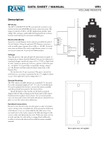
Remote Mounting
°e VR1 remote assembly mounts in a standard U.S. electrical
box with a minimum depth of 2.25" (5.5 cm). Use the flat head
#6 screws supplied with the kit to mount the remote assembly
and silk-screened front panel to the electrical box.
Install the knob so that the line on the knob is properly
aligned with the silk-screening on the front panel of the remote.
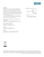
Install any Decora plate of your choice. For a secured installa-
tion, you may wish to leave the knobs off and use a blank Decora
plate to cover the remote after adjustment.
Euroblock Connections
Be sure to note the wire color of each input in order to facilitate
correct wiring to the controlled unit. If the ground or shield wire
is left shorter, it acts as a strain relief for the other wires. Con-
nect each wire to the 3-pin connector by fully inserting it in the
correct socket and tightening the screw. Make sure wires are free
of nicks and that the cable jacket is stripped back sufficiently
to allow it to lie in the electrical box with the remote assembly
inserted.
Vc
GND
Vr
4
0
2
6
8
10
LEVEL
Decora plate cover, not supplied.