Rheem 500 Series Installation Guide
Rheem 500 Series Manual
 |
View all Rheem 500 Series manuals
Add to My Manuals
Save this manual to your list of manuals |
Rheem 500 Series manual content summary:
- Rheem 500 Series | Installation Guide - Page 1
Dealer Installation and Start-Up Instructions 500 Series Thermostat Featuring Serial Communication (-)HC-TST501CMMS Manual 37-6943A 0830 - Rheem 500 Series | Installation Guide - Page 2
INSTRUCTIONS CAREFULLY BEFORE INSTALLING OR OPERATING THIS CONTROL AND SYSTEM COULD CAUSE PERSONAL INJURY AND/OR PROPERTY DAMAGE. Introduction to Thermostat and Communicating Supply air sensor out of range Coil Temperature Sensor Fault Outdoor Ambient Temperature Sensor Fault Board Failure Compressor - Rheem 500 Series | Installation Guide - Page 3
(over 1200 RPM) No Blower Communication Servo circuit open Servo control fault No Gas Valve Feedback Low Airflow Table of Contents Installation 4 Battery Location 4 Wiring Requirements 4 Quick Installation Steps 5 Installing Thermostat 5 Initial Power Up 6 Thermostat Setup 8 Set Current Time - Rheem 500 Series | Installation Guide - Page 4
batteries in the rear along the top of the thermostat. Reposition the thermostat over the base plate and gently snap into place. Wiring Requirements Each communicating device in the system has a four wire AC Installer Guide) Selectable Cooling Airflow Adjustments Select Blower Operation based on - Rheem 500 Series | Installation Guide - Page 5
• Mount thermostat base to wall. • Connect wires to thermostat base. • Remove battery tag to provide battery power to the thermostat. • Attach thermostat to base. • Turn on power to system. Allow approximately 1 minute for the system to configure. • Set the time • Select thermostat operating options - Rheem 500 Series | Installation Guide - Page 6
) FOUND. Note: If the thermostat display continuously shows "SEARCHING", check the wiring to the thermostat. Communications Systems The thermostat will recognize the system devices that are connected and the capacities to set the system up to the operating settings. The system has additional - Rheem 500 Series | Installation Guide - Page 7
Comments XXXX-XXXXXXXXXXXXXXXX Unit Model Number XXXXXXXXXXXXXXXXXXX Unit Serial Number (not available if control is replaced) XXXXXX Control Software Version Initial Power-Up Check System Operation Fan Operation • Turn power on to the system. • Press Run Schedule. • Press FAN until FAN On is - Rheem 500 Series | Installation Guide - Page 8
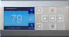
Thermostat Home Screen Display. Advanced Installer Configuration Menu Heat Pump User Menus Status Parameter Compressor Mode Comp Hi Pres SW Comp Lo Pres SW Outdr Temp Defrost, Time Delay, Off Closed, Open Closed, Open FLT, XXXF FLT, XXXF Comments Compressor Status System Mode of Operation Heat Pump - Rheem 500 Series | Installation Guide - Page 9
wire communications. It is only displayed when a conventional 24V thermostat input is active. Thermostat Setup Choose the System Setting (Cool, Off, Heat, Em, Auto) Touch the SYSTEM key to select: Cool: Thermostat controls Instructions for changing the programming are in the Homeowner User Guide. - Rheem 500 Series | Installation Guide - Page 10
Demand Dehumidification is selected, the thermostat will indicate the current humidity on the Menu Air Handler User Menus Status Parameter Auxiliary , XXXF, FLT Return Temp Supply Temp NA (if disabled), control has been powered Auxiliary Heat Hours of Operation Auxiliary Heat Cycles Continuous Fan Hours - Rheem 500 Series | Installation Guide - Page 11
% Heat Pump AC Stage Multiplier * Dipswitch status is not required when the system is set up for 4-wire communications. It is only displayed when a conventional 24V thermostat input is active. Thermostat Setup Select continuous FAN speed. Default is Medium. It can be set to High, Medium or Low - Rheem 500 Series | Installation Guide - Page 12
system power is off and thermostat is operating on battery only, Installer Configuration Menu Furnace User Menus (Cont.) 2 Week History control has been powered Low Heat Hours of Operation Low Heat Cycles High Heat Hours of Operation High Heat Cycles First Stage Cooling/Heat Pump Hours of Operation - Rheem 500 Series | Installation Guide - Page 13
User Menus Status I Parameter Indications Comments 1 Main Limit Closed, Open Main Limit Control Status MRLC Input Closed, Open Main Reset Limit Control Status HALC Input Closed, Open Heat Assist Limit Control Current Operating CFM Temp Rise NA, XXXF Difference between the Supply and - Rheem 500 Series | Installation Guide - Page 14
" to indicate maintenance is required. Advanced Installer Configuration Menu Thermostat User Menus Status Parameter Configuration Indications Comments HP - Heat Pump through its sequential mode of operation. This will reset ALL of the communicating system components to their factory set values. - Rheem 500 Series | Installation Guide - Page 15
is applicable only in the heat pump mode. When this feature is selected, the thermostat will switch to electric heat and shut off the compressor when the outside temperature falls below the HP balance point. In the Thermostat User Menu, use or to select the temperature which can be between 5 to 50 - Rheem 500 Series | Installation Guide - Page 16
at the new temperature until you touch Run Schedule or you manually adjust to another temperature. Non-Programmable Mode If Program days per week is set for 0 Days (Non-programmable) in the Thermostat Options Configuration Menu, the thermostat will not follow any program periods. Time of day and day - Rheem 500 Series | Installation Guide - Page 17
To change the Programmable Fan setting, see page 18 in the Homeowner User Guide. Check System Status If the Home Screen Display indicates "Call for Service" and "Check If the thermostat indicates "Call for Service" with "CHECK SYSTEM", the indoor unit is not detected or has failed to communicate. - Rheem 500 Series | Installation Guide - Page 18
when it is time for accessory maintenance if selected in the Thermostat Options Configuration Menu. When a reminder appears, it can and equipment operating information and options. Entering and Navigating the Advanced Installer Configuration Menu/Service Information On Equipment User Menu, touch or .
-
 1
1 -
 2
2 -
 3
3 -
 4
4 -
 5
5 -
 6
6 -
 7
7 -
8
-
9
-
10
-
11
-
12
-
13
-
14
-
15
-
16
-
17
-
18
 |
 |

Manual 37-6943A
0830
Dealer Installation
and Start-Up Instructions
500 Series Thermostat
Featuring Serial Communication
(-)HC-TST501CMMS