Rheem RAMP-JEZ Installation Instructions
Rheem RAMP-JEZ Manual
 |
View all Rheem RAMP-JEZ manuals
Add to My Manuals
Save this manual to your list of manuals |
Rheem RAMP-JEZ manual content summary:
- Rheem RAMP-JEZ | Installation Instructions - Page 1
THESE INSTRUCTIONS MAY RESULT IN IMPROPER INSTALLATION, ADJUSTMENT, SERVICE OR MAINTENANCE POSSIBLY RESULTING IN FIRE, ELECTRICAL SHOCK, PROPERTY DAMAGE, PERSONAL INJURY OR DEATH. (14.5 SEER MODELS & 14 OR 13 SEER MODELS IN CERTAIN MARKED SYSTEMS) ISO 9001:2000 DO NOT DESTROY THIS MANUAL PLEASE - Rheem RAMP-JEZ | Installation Instructions - Page 2
Tie-Down Method 7 Refrigerant Connections 8 Tools Required for Installing & Servicing R-410A Models 8 Specification of R-410A 8 Quick Reference for R- 16 High and Low Pressure Controls (HPC or LPC 18 Field Installed Accessories 18 Service 19 Trouble Shooting 20-22 Trouble Shooting Chart 23 - Rheem RAMP-JEZ | Installation Instructions - Page 3
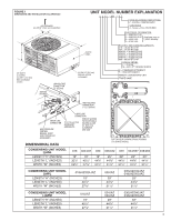
NUMBER EXPLANATION (-) A N L - 024 J A Z COOLING CONNECTION FITTING Z - SCROLL COMPRESSOR VARIATIONS A - Series = FULL FEATURED ACCESS PANEL ALLOW 24" [610 mm] SERVICE ACCESS CLEARANCE ELECTRICAL DESIGNATION J = 208/230V-1-60 } C = 208/230V-3-60 [Available only on D = 460V-3-60 (-)ANL- Models - Rheem RAMP-JEZ | Installation Instructions - Page 4
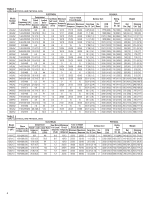
TABLE 1 (-)ANL ELECTRICAL AND PHYSICAL DATA ELECTRICAL PHYSICAL Model Number (-)ANL- Compressor Fuse or HACR Fan Motor Minimum Outdoor Coil Phase Rated Locked Full Load Circuit Circuit Breaker Frequency (Hz) Load Voltage (Volts) Amperes (RLA) Rotor Amperes (LRA) Amperes (FLA) Ampacity - Rheem RAMP-JEZ | Installation Instructions - Page 5
manual and any instructions packaged with separate equipment required to make up the system prior to installation. Retain this manual where contaminants are likely to be a problem, special attention should be given to but cannot violate minimum airflow and service access clearances. • Elevating the - Rheem RAMP-JEZ | Installation Instructions - Page 6
operating costs. • Locate the condenser where water run off will not create a problem with the equipment. Position the unit away from the drip edge of the and efficiency. Do not reduce the 60-inch discharge, or 24-inch service, clearances. • Do not obstruct the bottom drain opening in the condenser - Rheem RAMP-JEZ | Installation Instructions - Page 7
performance. Use the information in this Installation Instruction Manual and reference the applicable Engineering Specification Sheet FACTORY-PREFERRED TIE-DOWN METHOD FOR CONDENSING UNITS IMPORTANT: These instructions are intended as a guide to securing equipment for wind-load ratings of "120 MPH - Rheem RAMP-JEZ | Installation Instructions - Page 8
is to be made to prevent system contamination. TOOLS REQUIRED FOR INSTALLING & SERVICING R-410A MODELS Manifold Sets: -Up to 800 PSIG High side -Up to 250 PSIG Low Side -550 PSIG Low Side Retard Manifold Hoses: -Service Pressure Rating of 800 PSIG Recovery Cylinders: -400 PSIG Pressure Rating -Dept - Rheem RAMP-JEZ | Installation Instructions - Page 9
low-side with a 550 psig low-side retard. Hoses need to have a service pressure rating of 800 psig. Recovery cylinders need to have a 400 psig service GUIDE FOR R-410A • R-410A refrigerant operates at approximately 60% higher pressure (1.6 times) than R-22. Ensure that servicing INSTRUCTIONS. - Rheem RAMP-JEZ | Installation Instructions - Page 10
specifically designed for R-410A. LOCATION Do not install the indoor evaporator coil in the return duct system of a gas or oil furnace. Provide a service inlet to the coil for inspection and cleaning. Keep the coil pitched toward the drain connection. ! CAUTION When coil is installed over a finished - Rheem RAMP-JEZ | Installation Instructions - Page 11
kinking. • Route the tubing using temporary hangers, then straighten the tubing and install permanent hangers. Line must be adequately supported. • The vapor line must be insulated to prevent dripping (sweating) and prevent performance losses. Armaflex and Rubatex are satisfactory insulations - Rheem RAMP-JEZ | Installation Instructions - Page 12
braze any fitting with the TEV sensing bulb attached. • Braze the tubing between the outdoor unit and indoor coil. Flow dry nitrogen into a service port and through the tubing while brazing. • After brazing - use an appropriate heatsink material to cool the joint and remove any flux residue. • The - Rheem RAMP-JEZ | Installation Instructions - Page 13
TABLE 6 LIQUID LINE SIZE - OUTDOOR UNIT ABOVE INDOOR COIL Liquid Line Size Line Size System Connection Line Size Outdoor Unit Above Indoor Coil (Cooling Only - Does not apply to Heat Pumps) Capacity Size (Inch O.D.) Total (Inch I.D.) 25 50 75 100 125 150 Minimum Vertical Separation - - Rheem RAMP-JEZ | Installation Instructions - Page 14
the service panel and adjusted, if required. Allow a minimum of 5 minutes running. Before analyzing charge, see the instructions on the unit service panel . Excessive indoor airflow increases the possibility of high humidity problems. Low indoor airflow reduces total capacity, and causes coil icing. - Rheem RAMP-JEZ | Installation Instructions - Page 15
Liquid pressure method is used for charging systems in the cooling mode when an expansion valve is used on the evaporator. The service port on the liquid service valve (small valve) is used for this purpose. Read and record the outdoor ambient temperature entering the condensing unit, and the liquid - Rheem RAMP-JEZ | Installation Instructions - Page 16
interconnecting tubing and evaporator coil is adequate; otherwise, evacuate the entire system. Use the factory charge shown in Table 1 of these instructions or unit data plate. Note that charge value includes charge required for 15 ft. of standard size interconnecting liquid line. Calculate actual - Rheem RAMP-JEZ | Installation Instructions - Page 17
between thermostat and outdoor unit. CONTROL WIRING (See Figure 4) If the low voltage control wiring is run in conduit with the power supply, Class I insulation is required. Class II insulation is required if run separate. Low voltage wiring may be run through the insulated bushing provided in the - Rheem RAMP-JEZ | Installation Instructions - Page 18
the compressor from operating in pressure ranges which can cause damage to the compressor. Both controls are in the low voltage control cir-cuit. High pressure control (HPC) is a manual reset which opens near 610 PSIG. Do not reset arbitrarily without first determining what caused it to trip. The - Rheem RAMP-JEZ | Installation Instructions - Page 19
dimming. TIME DELAY CONTROL (TDC) The time delay (TDC) is in the low voltage control circuit. When the compressor shuts off due to a power failure or UNIT COVER BEFORE OPERATING OUTDOOR UNIT CAN CAUSE COMPONENTS TO FAIL. SERVICE SINGLE-POLE COMPRESSOR CONTACTOR (CC) Single-pole contactors are used - Rheem RAMP-JEZ | Installation Instructions - Page 20
TROUBLE SHOOTING In diagnosing common faults in the air conditioning system, it is useful to present the logical pattern of thought that is used by experienced technicians. The charts which follow are not intended to be an answer to all problems, but only to guide your thinking as you attempt to - Rheem RAMP-JEZ | Installation Instructions - Page 21
MECHANICAL CHECKS FLOW CHART Unit Running? High Head Pressure YES Pressure problems? Low Head Pressure Dirty Condenser Coil Low on Charge Inoperative Outdoor Fan Open IPR Valve Overcharge Low Ambient Temperature Recirculation of Condenser Air Inoperative Compressor Valves Non-condensibles - Rheem RAMP-JEZ | Installation Instructions - Page 22
TROUBLESHOOTING TIPS SYSTEM PROBLEM INDICATORS DISCHARGE PRESSURE SUCTION PRESSURE SUPERHEAT SUBCOOLING COMPRESSOR AMPS Overcharge High High Low High High Undercharge Low Low High Low Low Liquid Restriction (Drier) Low Low High High Low Low Evaporator Airflow Low Low Low - Rheem RAMP-JEZ | Installation Instructions - Page 23
TROUBLE SHOOTING CHART ! WARNING DISCONNECT ALL POWER TO UNIT BEFORE SERVICING. CONTACTOR MAY BREAK ONLY ONE SIDE. • Flowcheck piston size too large • Defective Compressor valves • Incorrect capillary tubes • Low indoor airflow • Operating below 65°F outdoors • Moisture in system • Excessive load • - Rheem RAMP-JEZ | Installation Instructions - Page 24
FIGURE 4 SINGLE-PHASE WIRING DIAGRAM 24 - Rheem RAMP-JEZ | Installation Instructions - Page 25
FIGURE 5 THREE-PHASE WIRING DIAGRAM (C, D & Y VOLTAGES) 25 - Rheem RAMP-JEZ | Installation Instructions - Page 26
FIGURE 6 26 - Rheem RAMP-JEZ | Installation Instructions - Page 27
27 - Rheem RAMP-JEZ | Installation Instructions - Page 28
28 CM 0908
-
 1
1 -
 2
2 -
 3
3 -
 4
4 -
 5
5 -
 6
6 -
 7
7 -
8
-
9
-
10
-
11
-
12
-
13
-
14
-
15
-
16
-
17
-
18
-
19
-
20
-
21
-
22
-
23
-
24
-
25
-
26
-
27
-
28
 |
 |
92-21354-51-08
SUPERSEDES 92-21354-51-07
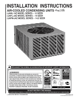
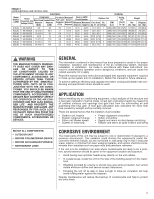
AIR-COOLED CONDENSING UNITS
(-)ANL-*AZ MODEL SERIES – 13 SEER
(-)APL-JAZ MODEL SERIES – 14 SEER
(-)APM-JAZ MODEL SERIES – 14.5 SEER
INSTALLATION INSTRUCTIONS
RECOGNIZE THIS SYMBOL AS AN INDICATION OF IMPORT
TION!
!
DO NOT DESTROY THIS MANUAL
PLEASE READ CAREFULLY AND KEEP IN A SAFE PLACE FOR FUTURE REFERENCE BY A SERVICEMAN
WARNING
!
ANT SAFETY
INFORMA
THESE INSTRUCTIONS ARE INTENDED AS AN AID TO
QUALIFIED, LICENSED SERVICE PERSONNEL FOR PROPER
INSTALLATION, ADJUSTMENT AND OPERATION OFTHIS
UNIT.READ THESE INSTRUCTIONS THOROUGHLY BEFORE
ATTEMPTING INSTALLATION OR OPERATION. FAILURE TO
FOLLOWTHESE INSTRUCTIONS MAY RESULT IN IMPROPER
INSTALLATION, ADJUSTMENT,SERVICE OR MAINTENANCE
POSSIBLY RESULTING INFIRE,
ELECTRICAL SHOCK,
PROPERTY DAMAGE, PERSONAL INJURY OR DEATH.
[ ] INDICATES METRIC CONVERSIONS
efrigerant
ISO 9001:2000
(14.5 SEER MODELS
& 14 OR 13 SEER
MODELS IN CERTAIN
MARKED SYSTEMS)