Ryobi AC04145 Operation Manual
Ryobi AC04145 Manual
 |
View all Ryobi AC04145 manuals
Add to My Manuals
Save this manual to your list of manuals |
Ryobi AC04145 manual content summary:
- Ryobi AC04145 | Operation Manual - Page 1
For purposes of the illustrations in this manual, only standard replacement blades are shown. in these instructions, take your unit to a qualified service center. ) Fig. 2 B G G A B G G C D E F A - Blade carrier (support de la lame, soporte de la hoja) B - Shaft (arbre, eje) C - Blade (lame - Ryobi AC04145 | Operation Manual - Page 2
autre des tâches décrites dans les présentes instructions, confiez l'unité à un centre de réparations bien appuyée, la lame devrait être à plat contre le support de la lame. Remettez l'isolant de lame et l'écarteur el usuario debe leer y entender el manual del operador para su podadora y esta hoja
-
 1
1 -
 2
2
 |
 |
LAWN MOWER BLADE
AC04020/AC04021/AC04145
For use with RYOBI
®
40 Volt
20 in. Lawn Mower ONLY
991000488
4-30-18 (REV:04)
NOTE:
For purposes of the illustrations in this manual, only standard replacement
blades are shown. However, bagging blades would install in the same way.
WARNING!
To reduce the risk of injury, user must read and understand the operator’s manual
for their lawn mower and this instruction sheet. Always wear eye protection with
side shields marked to comply with ANSI Z87.1. Ensure compatibility and fit
before using this accessory. Do not use this accessory if a part is damaged or
missing. If you are not comfortable performing any of the functions described in
these instructions, take your unit to a qualified service center.
WARNING:
Always protect hands by wearing heavy gloves and/or wrapping the cutting edges
of the blade with rags and other material when performing blade maintenance.
Contact with the blade could result in serious personal injury.
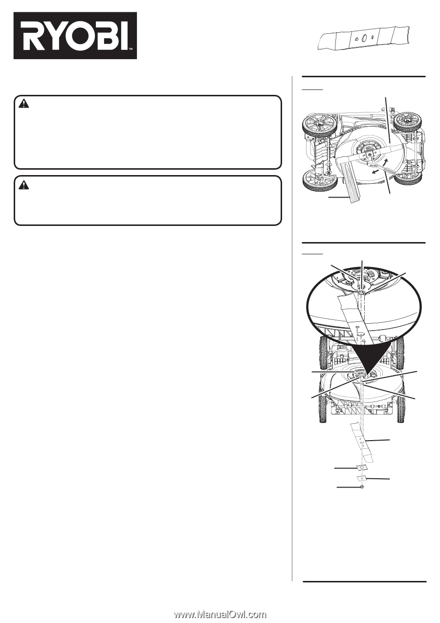
REPLACING THE CUTTING BLADE
See Figures 1 - 2.
Stop the motor and remove the fuse key. Allow blade to come to a complete
stop.
Remove the battery pack.
Turn the mower on its side.
Wedge a block of wood between the blade and mower deck to prevent the blade
from turning.
Loosen the blade nut by turning it counterclockwise (as viewed from bottom of
mower) using a 15 mm wrench or socket (not provided).
Remove the blade nut, spacer, blade insulator, and blade.
Make certain the blade carrier is pushed completely against the motor shaft.
Place the new blade on the shaft against the blade carrier. Ensure blade is
properly seated with shaft going through center blade hole and the two blade
posts inserted into their respective holes on the blade. Make sure it is installed
with the curved ends pointing up toward the mower deck and not down toward
the ground. When seated properly, the blade should be flat against the blade
carrier.
Replace the blade insulator and spacer, then thread the blade nut on the shaft
and finger tighten.
NOTE:
Make certain all parts are replaced in the exact order in which they were
removed.
Torque the blade nut down clockwise using a torque wrench (not provided) to
ensure the bolt is properly tightened. The recommended torque for the blade nut
is 350-400 in. lbs.
Fig. 1
A - Blade (lame, hoja)
B - Wrench (clé, llave)
C - Block of wood (pièce de bois, bloque de
madera)
A
B
C
Fig. 2
A - Blade carrier (support de la lame, soporte
de la hoja)
B - Shaft (arbre, eje)
C - Blade (lame, hoja)
D - Blade insulator (isolant de lame, aislante
de hoja)
E - Spacer (entretoise, separador)
F - Blade nut (écrou de lame, tuerca de la
hoja)
G - Blade posts (tiges pour lame, montantes
de cuchilla)
G
G
F
E
C
D
A
B
B
G
G
TECHTRONIC INDUSTRIES POWER EQUIPMENT
1428 Pearman Dairy Road
Anderson, SC 29625, USA
1-800-860-4050
www.ryobitools.com