Ryobi ACRM005 Operation Manual
Ryobi ACRM005 Manual
 |
View all Ryobi ACRM005 manuals
Add to My Manuals
Save this manual to your list of manuals |
Ryobi ACRM005 manual content summary:
- Ryobi ACRM005 | Operation Manual - Page 1
ACRM005 BAGGING KIT FOR USE WITH RYOBI ELECTRIC ZERO TURN MOWER WARNING: To reduce the risk of injury, user must read and understand the operator's manual for their riding lawn mower before using this accessory. Save these instructions. Refer to them frequently and use them to instruct other users. - Ryobi ACRM005 | Operation Manual - Page 2
WARNING: If raising the mower to access the blades, make sure the mower is properly secured and the parking brake is set before proceeding. Failure to properly secure the mower could cause it to fall, resulting in possible death or serious personal injury. Wedge a block of wood between the blade - Ryobi ACRM005 | Operation Manual - Page 3
FRAME SHAFTS FRAME COVER COVER OPENINGS HOLE UPPER TUBE Fig. 5 COVER BAGS LOWER TUBE Fig. 8 Fig. 6 LATCH UPPER TUBE TAB LATCH Fig. 7 LATCH Fig. 9 LOWER TUBE Fig. 10 - Ryobi ACRM005 | Operation Manual - Page 4
care when mowing on slopes with the bagging kit installed. Never attempt to tow with the bagging kit installed. Failure to follow these instructions can result in death or serious personal injury. BAG FULL INDICATOR WARNING: Be especially careful before and when backing with the bagging kit - Ryobi ACRM005 | Operation Manual - Page 5
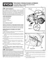
D'ENSACHAGE ACRM005 À UTILISER AVEC LA TONDEUSE ÉLECTRIQUE À BRAQUAGE ZÉRO RYOBI AVERTISSEMENT : Pour réduire les risques de blessure, l'utilisateur doit lire et comprendre le manuel d'utilisation de son tondeuse électrique autoportée avant d'employer cet accessoire. Conserver ces instructions. Les - Ryobi ACRM005 | Operation Manual - Page 6
le bouton d'enclenchement de lame est enfoncé. Arrêtez le moteur, retirez la clé de démarrage et enclencher le frein à main. n Insérer le support d'ensacheuse dans le trou situé à l'arrière et du côté droit de la tondeuse, comme illustré. n Installer la goupille d'attelage dans le trou situé au - Ryobi ACRM005 | Operation Manual - Page 7
ARBRES DU CHÂSSIS CHÂSSIS COUVERCLE OUVERTURE DU COUVERCLE COUVERCLE Fig. 5 SACS TROU TUBE SUPÉRIEUR TUBE INFÉRIEUR Fig. 8 Fig. 6 LOQUET TUBE SUPÉRIEUR LANGUETTE LOQUET Fig. 9 Fig. 7 n Installer le tube d'ensachage inférieur du côté de la buse de décharge en plaçant l'ouverture sur la - Ryobi ACRM005 | Operation Manual - Page 8
est installée. Ne jamais essayer de remorquer alors que l'ensemble de ramassage est installé. Des blessures graves ou mortelles peuvent survenir si ces instructions ne sont pas respectées. INDICATEUR DE SAC PLEIN AVERTISSEMENT : Une prudence accrue est requise avant et pendant la marche arrière - Ryobi ACRM005 | Operation Manual - Page 9
JUEGO PARA EMBOLSAR ACRM005 PARA USAR CON LA PODADORA ELÉCTRICA DE GIRO CERO RYOBI ADVERTENCIA: Para reducir el riesgo de lesiones, el usuario debe leer y comprender el manual del operador de la podadora de pasto tipo tractor antes de usar este accesorio. Guarde estas instrucciones. Consúltelas - Ryobi ACRM005 | Operation Manual - Page 10
NOTA: Si es necesario, levante la podadora colocando un elevador o utilizando un gato hidráulico y un gato estabilizador, o remueva la base de corto tal como se describe en la sección anterior antes de tener acceso a las cuchillas. ADVERTENCIA: Si levanta la podadora para acceder las cuchillas, aseg - Ryobi ACRM005 | Operation Manual - Page 11
EJES DEL BASTIDOR BASTIDOR CUBIERTA ABERTURAS DE LA CUBIERTA Fig. 5 CUBIERTA BOLSAS ORIFICIO TUBO SUPERIOR TUBO INFERIOR Fig. 8 Fig. 6 PESTILLO TUBO SUPERIOR LENGÜETA PESTILLO Fig. 9 Fig. 7 PESTILLO TUBO INFERIOR Fig. 10 n I nstale la parte superior del tubo superior para embolsadora ( - Ryobi ACRM005 | Operation Manual - Page 12
CÓMO USAR EL JUEGO PARA EMBOLSAR Vea las figuras 11 y 12. ADVERTENCIA: Los accesorios agregados pueden afectar la estabilidad de la podadora si se usa en pendientes. Tenga sumo cuidado cuando pode en pendientes si el juego para embolsar está instalado. No intente nunca remolcar con el kit de la
-
 1
1 -
 2
2 -
 3
3 -
 4
4 -
 5
5 -
 6
6 -
 7
7 -
8
-
9
-
10
-
11
-
12
 |
 |
ACRM005 BAGGING KIT
FOR USE WITH RYOBI ELECTRIC ZERO TURN MOWER
WARNING:
To reduce the risk of injury, user must read and understand
the operator’s manual for their riding lawn mower before
using this accessory. Save these instructions. Refer to them
frequently and use them to instruct other users. If you loan
someone this product, loan them these instructions also.
PACKING LIST
Bagging Blades (2)
Bagger Bracket
Hitch Pin
Bagger Cover
Bags (2)
Upper Bagger Tube
Lower Bagger Tube
INSTALLING THE BAGGING KIT
This kit includes a bagger and special mower blades designed
to be used when bagging. Install the blades first, then install
the bagging kit.
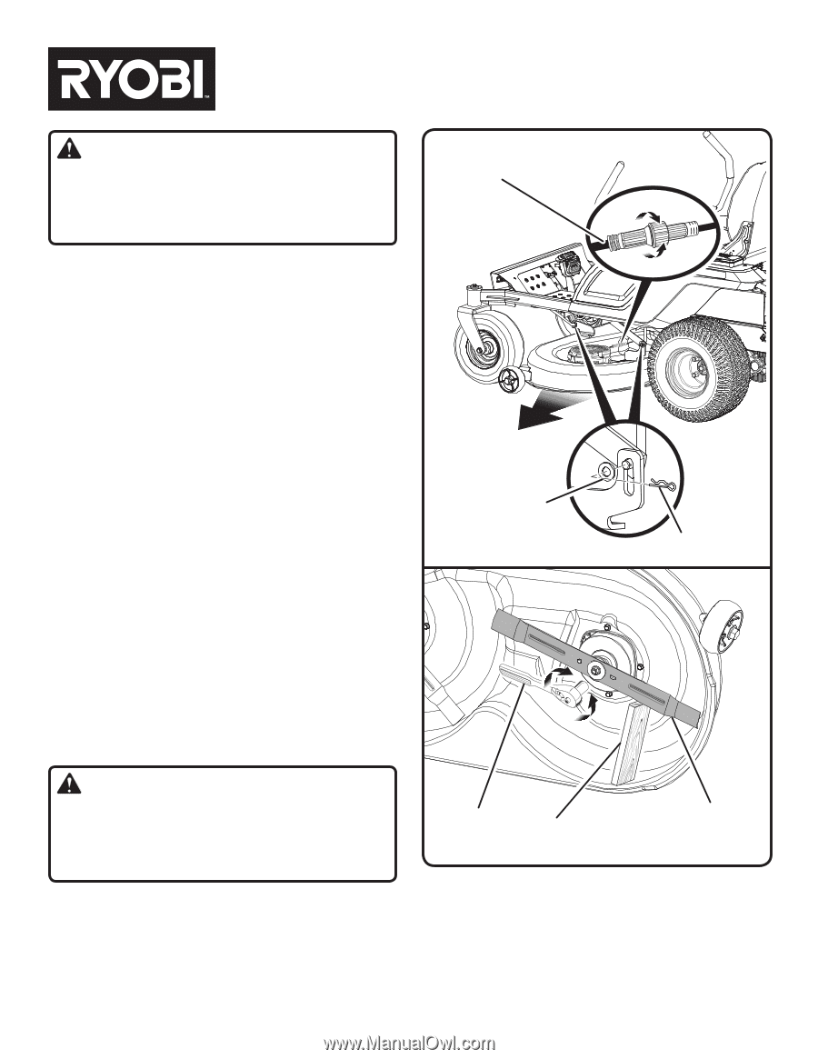
REMOVING THE CUTTING DECK
See Figure 1.
If desired, the cutting deck can be removed from the mower to
make accessing the blades easier when changing.
Make sure drive levers are in open position and blade engage
knob is down.
Stop the motor, remove the start key, and set the parking
brake.
Disconnect both cables that connect the cutting deck to the
mower.
Lower the cutting deck to its lowest position.
Remove the 3 hitch pins and washers that secure the cutting
deck in place.
Slide the deck out from under the mower.
Reverse the process to reattach the cutting deck to the
mower.
INSTALLING BAGGING BLADES
See Figures 2 - 3.
WARNING:
Only use replacement blades and blade bolts authorized
by the manufacturer of your riding mower. Unauthorized
blades and/or blade bolts could break, allowing the blade
to come loose, resulting in possible serious personal injury
and damage to the mower.
NOTE:
Make certain all parts are replaced in the exact order in
which they were removed.
Make sure drive levers are in open position and blade engage
knob is down.
Stop the motor, remove the start key, and set the parking
brake.
Raise the height of the cutting deck to its highest position
to allow access to blades.
NOTE:
If necessary, raise the mower by placing on a lift or
using a jack and jack stands, or remove the cutting deck
as described in the previous section to gain access to the
blades.
Fig. 1
Fig. 2
BLOCK OF WOOD
BLADE
WRENCH
CUTTING
DECK
HITCH PIN
WASHER
CABLE (x2)