Ryobi AP1301 English Manual - Page 13
Mounting The Planer, Installing Depth Adjustment Handle - 13 in planer
 |
View all Ryobi AP1301 manuals
Add to My Manuals
Save this manual to your list of manuals |
Page 13 highlights
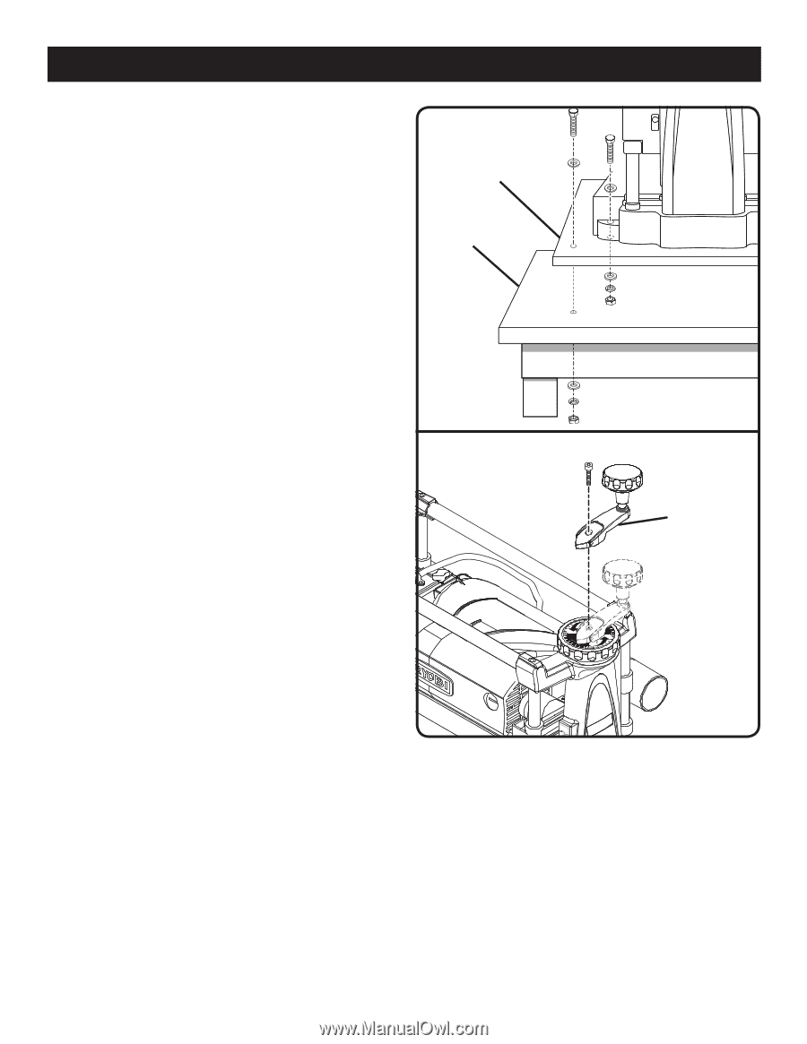
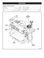
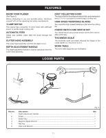
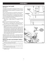
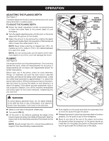
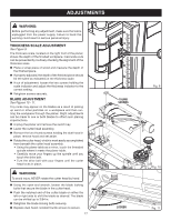
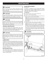
ASSEMBLY MOUNTING THE PLANER See Figure 4. If the planer is to be used in a permanent location, it is recommended you secure it to a workbench or to a mounting board that can be easily clamped to a workbench or other stable surface. When mounting the planer to a workbench, holes should be drilled through the supporting surface of the workbench. When mounting the planer to a mounting board, the board should be of sufficient size to avoid tipping while planer is in use. Any good grade plywood or chipboard with a 3/4 in. minimum thickness is recommended. Mark holes on surface where planer is to be mounted using holes in planer base as a template for hole pattern. Drill four holes through the mounting surface. Place planer on mounting surface, aligning holes in the planer base with holes drilled in the mounting surface. Insert four bolts (not included) and tighten securely with lock washers and hex nuts (not included). NOTE: All bolts should be inserted from the top. Install the lock washers and hex nuts from the underside of the mounting surface. If lag bolts are used, make sure they are long enough to go through holes in planer base and material the planer is being mounted to. If machine bolts are used, make sure bolts are long enough to go through holes in planer base, the material being mounted to, and the lock washers and hex nuts. Supporting surface where planer is mounted should be examined carefully after mounting to insure that no movement during use can result. If any tipping or walking is noted, secure workbench or support surface before beginning planing operation. INSTALLING DEPTH ADJUSTMENT HANDLE See Figure 5. Locate the hex key, depth adjustment handle, and hex head screw among the loose parts. Place the depth adjustment handle onto the depth gauge shaft. Insert the screw through the hole in the handle and into the threaded opening in the shaft. Using the hex key, rotate the screw clockwise to tighten handle securely. MOUNTING BOARD WORKBENCH Fig. 4 DEPTH ADJUSTMENT HANDLE WITH SCREW Fig. 5 13
-
 1
1 -
2
-
3
-
4
-
5
-
6
-
7
-
 8
8 -
 9
9 -
 10
10 -
 11
11 -
 12
12 -
 13
13 -
 14
14 -
 15
15 -
 16
16 -
 17
17 -
 18
18 -
19
-
20
-
21
-
22
 |
 |