Ryobi DP121L English Manual
Ryobi DP121L Manual
 |
View all Ryobi DP121L manuals
Add to My Manuals
Save this manual to your list of manuals |
Ryobi DP121L manual content summary:
- Ryobi DP121L | English Manual - Page 1
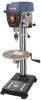
OPERATOR'S MANUAL 12 in. DIGITAL DRILL PRESS DP121l Your drill press has been engineered and manufactured to our high standard for dependability, ease of operation, and operator safety. When properly cared for, it will give you years of rugged, trouble-free performance. WARNING: To reduce the risk - Ryobi DP121L | English Manual - Page 2
Rules...3-4 Specific Safety Rules...5 Symbols...6-7 Electrical...8 Glossary of Terms...9 Features...10-11 Tools Needed...11 Loose Parts...12 Assembly...13-17 Operation...18-20 Adjustments...21 Maintenance...22 Troubleshooting...23 Parts Ordering / Service...Back - Ryobi DP121L | English Manual - Page 3
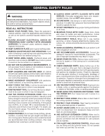
INSTRUCTIONS KNOW YOUR POWER TOOL. Read the operator's manual carefully. Learn the applications and limitations as well as the specific contact tool or extension cord while operating. MAKE WORKSHOP CHILDPROOF with padlocks, master switches, or by removing starter keys. DON'T FORCE THE TOOL. - Ryobi DP121L | English Manual - Page 4
. WHEN SERVICING use only identical replacement parts. Use of any other parts may create a hazard or cause product damage. USE ONLY RECOMMENDED ACCESSORIES listed in this manual or addendums. Use of accessories that are not listed may cause the risk of personal injury. Instructions for safe - Ryobi DP121L | English Manual - Page 5
SURE THE BELT GUARD IS DOWN AND THE CHUCK IS INSTALLED PROPERLY. LOCK THE MOTOR SWITCH OFF WHEN LEAVING THE DRILL PRESS. Do not perform layout, assembly, or set-up work on the table while the cutting tool is rotating, switched on, or connected to a power source. SAVE THESE INSTRUCTIONS. Refer to - Ryobi DP121L | English Manual - Page 6
per minute Wet Conditions Alert Do not expose to rain or use in damp locations. Read The Operator's Manual To reduce the risk of injury, user must read and understand operator's manual before using this product. Eye Protection Safety Alert No Hands Symbol Hot Surface Always wear safety goggles - Ryobi DP121L | English Manual - Page 7
servicing, use only identical replacement parts. WARNING: To avoid serious personal injury, do not attempt to use this product until you read thoroughly and understand completely the operator's manual. Save this operator's manual and review frequently for continuing safe operation and instructing - Ryobi DP121L | English Manual - Page 8
line intended only for lights cannot properly carry a power tool motor. Wire that is heavy enough for a short distance will be too light for a greater distance. A line that can support one power tool may not be able to support two or three tools. Grounding Instructions In the event of a malfunction - Ryobi DP121L | English Manual - Page 9
other than 90°. Non-Through Cuts Any cutting operation where the blade does not extend completely through the thickness of the workpiece. Pilot Hole (drill presses) A small hole drilled in a workpiece that serves as a guide for drilling large holes accurately. Push Blocks and Push Sticks Devices - Ryobi DP121L | English Manual - Page 10
product specifications Chuck 1/2 in. Input 120 Volt, 60Hz, AC Only, 5 Amps Motor 1/3 HP Induction No Load Speed 500-3,000 r/min (RPM) Depth 12 in. Spindle Travel 3 in. Table Size 10-3/4 in. dia. Table Movement 45° bevel, 360° swivel Overall Height 35 in. Net Weight 91 lbs. laser - Ryobi DP121L | English Manual - Page 11
the tool. CHUCK TOOL The chuck tool is used to remove the chuck and chuck spindle. exactline™ laser The Exactline™ laser makes accurate, precision drilling simple and easy. feed handles Feed handles raise and lower the chuck and bit during the drilling operation. Motor Your drill press is equipped - Ryobi DP121L | English Manual - Page 12
with the drill press: Head Assembly 1 Column Assembly 1 Table 1 Table Support 1 Base 1 Hex Key (3 mm, 4 mm, and 5 mm 3 Hex Bolts (M8 4 Feed Handles 3 Worm Gear 1 Spindle Lock Lever 1 Table Adjustment Handle 1 Table Lock Handle 1 Variable Speed Lever 1 Chuck Tool 1 Chuck 1 Chuck Key - Ryobi DP121L | English Manual - Page 13
UNPACKING This product requires assembly. Carefully remove the tool and any accessories from the box tighten using an adjustable wrench. WARNING: If any parts are damaged or missing do not operate this tool until the missing parts are replaced. Failure to heed this warning could result in - Ryobi DP121L | English Manual - Page 14
shaft aligns with the set screw. Using the hex key, tighten the set screw on the table adjustment handle. Locate the table lock handle. Insert it into the threaded hole at the rear of the table support and tighten by hand. Remove protective covering from the table and discard. Place the table - Ryobi DP121L | English Manual - Page 15
tap the chuck into place using a mallet or hammer. Fit the arbor into the spindle shaft turning it to the right until it slips into place and tap with mallet using a piece of wood. NOTE: Wipe the surfaces of the arbor and spindle shaft with a clean, dry cloth before assembly to remove excess - Ryobi DP121L | English Manual - Page 16
worklight bulb See Figure 12. The integrated worklight can be used to help illuminate the work area. The worklight requires a 15-watt, 120-volt, candelabra-base bulb (not included). To install, insert the bulb into the worklight receptacle and twist clockwise to secure. Mounting the Drill press See - Ryobi DP121L | English Manual - Page 17
on a piece of scrap wood. Insert a small drill bit into the chuck and align its tip to the intersection of the lines of the "X". Secure the board to the table. Turn on the laser and verify the laser lines align with the "X" on the workpiece. If the laser lines do not align, loosen the set - Ryobi DP121L | English Manual - Page 18
With the switch key inserted into the switch, lift the switch to turn ON (l ). To turn the drill press off: With the switch key inserted into the switch, push the switch down to turn OFF ( O ). To lock the drill press: Place the switch in the OFF ( O ) position. Remove the switch key from the - Ryobi DP121L | English Manual - Page 19
OPERATION SELF-EJECTING CHUCK KEY See Figure 17. The self-ejecting chuck key ensures the chuck key is removed from the chuck before the drill press is turned on. In order to loosen or tighten the chuck using the chuck key, push the key into the key hole located on the chuck. Rotate the key - Ryobi DP121L | English Manual - Page 20
. Plug the electrical cord into power supply and turn the switch ON. Make sure spindle rotates freely. With the motor running, change the spindle speed with the variable speed lever. NOTE: The digital display on the front of the drill press will give you the exact spindle speed. Use the - Ryobi DP121L | English Manual - Page 21
drill press is equipped with a tilting table that allows you to drill drilling depth when you need to drill a number of holes to exactly the same depth: Loosen the lock knob and the spindle lock lever. Rotate depth gauge to the desired setting. Retighten the lock knob securely using the hex key - Ryobi DP121L | English Manual - Page 22
shields during power tool operation or when blowing dust. If operation is dusty, also wear a dust mask. WARNING: To prevent accidental starting that could cause possible serious personal injury, turn off the tool, remove the switch key, and unplug the drill press before performing any maintenance - Ryobi DP121L | English Manual - Page 23
troubleshooting Problem Noisy operation Bit burns or smokes Excessive drill runout or wobble Drill bit binds in workpiece Workpiece support loosens Possible Cause Solution Incorrect belt tension Dry spindle Loose spindle pulley or motor pulley Adjust belt tension. Lubricate spindle. Tighten set - Ryobi DP121L | English Manual - Page 24
OPERATOR'S MANUAL 12 in. DIGITAL DRILL PRESS DP121l • SERVICE Now that you have purchased your tool, should a need ever exist for repair parts or service, simply contact your nearest Authorized Service Center. Be sure to provide all pertinent facts when you call or visit. Please call 1-800-525-2579
-
 1
1 -
 2
2 -
 3
3 -
 4
4 -
 5
5 -
 6
6 -
 7
7 -
8
-
9
-
10
-
11
-
12
-
13
-
14
-
15
-
16
-
17
-
18
-
19
-
20
-
21
-
22
-
23
-
24
 |
 |

Your drill press has been engineered and manufactured to our high standard for dependability, ease of operation, and
operator safety. When properly cared for, it will give you years of rugged, trouble-free performance.
WARNING:
To reduce the risk of injury, the user must read and understand the operator’s manual before using
this product.
Thank you for your purchase.
SAVE THIS MANUAL FOR FUTURE REFERENCE
OPERATOR’S MANUAL
12 in. DIGITAL DRILL PRESS
DP121L