Ryobi GD126 Operation Manual
Ryobi GD126 Manual
 |
View all Ryobi GD126 manuals
Add to My Manuals
Save this manual to your list of manuals |
Ryobi GD126 manual content summary:
- Ryobi GD126 | Operation Manual - Page 1
in range or install a Wi-Fi range extender. If you do not have internet access, troubleshoot your Wi-Fi router according to the manufacturer's instructions. An internet connected Wi-Fi network signal is required to operate this product. Download the RYOBI™ Garage Door Opener Accessory System™ App - Ryobi GD126 | Operation Manual - Page 2
WI-FI ( ) du concentrateur relais pendant trois secondes puis relâchez-le et démarrez l'application Garage Door Opener Accessory System™ de RYOBI™. Suivez les instructions fournies dans l'application pour connecter le concentrateur relais à votre réseau domestique et à l'application. Pour plus
-
 1
1 -
 2
2
 |
 |

WI-FI CONNECTIVITY
SYSTEM ADDENDUM
FOR RYOBI GARAGE
DOOR OPENERS
The way the RYOBI
™
Garage Door Opener Accessory System
™
App interacts with your garage door opener has changed. Now,
to control your garage door from your smartphone, you will need
to install this Wi-Fi connectivity system. Once installed, you will
be able to control and track the movement of your garage door
using your smartphone.
WARNING:
To reduce the risk of injury, do not attempt to use this product
until you have read thoroughly and understand completely this
addendum and the operator’s manual for your garage door opener.
WARNING:
This system is designed to work with RYOBI
™
garage door
openers only.
Attempting to use this system with other types
of garage door openers can cause the system or garage door
opener to function improperly which can result in death or serious
personal injury.
WARNING:
To reduce the risk of injury to persons – The Wi-Fi connectivity
system should only be used with sectional garage doors.
DO NOT
install this product on single-panel garage doors.
WARNING:
Devices or features, such as the Wi-Fi connectivity system and the
RYOBI
™
Garage Door Opener Accessory System
™
App that allow
you to open and close the garage without the garage door being
in view, should only be used with sectional garage doors.
Fig. 1
Fig. 3
Fig. 5
A - Battery cover (couvercle des piles, tapa de las baterías)
B - Door sensor (détecteur de porte, sensor del portón)
C - Slot (fente, ranura)
D - Coin (cléfs, monedas)
E - AAA battery (AAA pile, batería AAA)
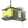
A - Relay hub (concentrateur relais, módulo relé)
A
D
C
B
E
A - Door hinge (charnière de porte, bisagra del portón)
B - Battery cover (couvercle des piles, tapa de las baterías)
C - Screws (vis, tornillos)
D - Door sensor (détecteur de porte, sensor del portón)
A - Door sensor (détecteur de porte, sensor del portón)
B - Blue LED (DEL bleu, luz LED azul)
C - Link (
) button [bouton Link (
), botón Link (
))
D - Relay hub (concentrateur relais, módulo relé)
E - Green LED (DEL vert, luz LED verde)
F - Wi-Fi (
) button [bouton Wi-Fi (
), botón Wi-Fi (
)]
C - Relay hub (concentrateur relais, módulo relé)
D - Smartphone (téléphone intelligent, teléfono inteligente)
A - Garage door opener (ouvre-porte de garage, sistema
de apertura para portón de garaje)
B - Door sensor (détecteur de porte, sensor del portón)
B
A
Fig. 2
Fig. 4
A
A
C
C
F
E
B
B
A
D
C
B
A
D
PACKING LIST
Door Sensor, Relay Hub, Self-Tapping Screws, AAA Battery, and
Addendum.
BEFORE INSTALLING THE RYOBI
™
WI-FI
CONNECTIVITY SYSTEM
Familiarize yourself with the
Wi-Fi Communication Information
in your garage door opener manual.
Assemble and mount the garage door opener as described in the
garage door opener manual.
Connect the garage door opener to an AC power supply and
perform all of the items on the
Installation Verification Checklist
,
refer to your garage door opener manual for details.
Using a smartphone, confirm that your home's Wi-Fi network is
connected to the internet and can be accessed from inside your
garage. If the network can't be accessed, move your Wi-Fi router
until the network is in range or install a Wi-Fi range extender.
If you do not have internet access, troubleshoot your Wi-Fi
router according to the manufacturer's instructions.
An internet
connected Wi-Fi network signal is required to operate this
product.
Download the RYOBI
™
Garage Door Opener Accessory System
™
App from the
App Store
or
Google Play Store
.
Follow the instructions provided in the app to connect the garage
door opener to your home network and the app. For more
information, visit www.ryobitools.com.
After a connection is established, you’ll be able to monitor the status
of connected accessories (if applicable) from your smartphone.
NOTE: You will not be able to track and control the movement
of your garage door from your smartphone until the Wi-Fi
connectivity system is installed and connected.
INSTALLING THE DOOR SENSOR
See Figures 1 - 2.
Lower the garage door completely.
Separate the sensor from the battery cover by inserting the edge
of a coin into the slot on the bottom and twisting.
Install a new AAA battery inside the door sensor according to the
polarity indicators.
NOTE:
After the Wi-Fi connectivity system is installed and
connected, you’ll receive a notification through the app whenever
the AAA battery charge is low.
Position the battery cover in the upper left or upper right corner of
the garage door beneath one of the door hinges.
NOTE:
For best performance, the cover should be placed as close
to the left or right edge of the door and as high as possible (see
figure 5).
Hold the battery cover against the door and secure in place using
self-tapping screws. Tighten screws securely.
NOTE:
The cover should be installed with the arrow facing up.
Carefully position the door sensor over the battery cover and snap
into place.
CONNECTING THE RELAY HUB TO YOUR WI-FI
HOME NETWORK
See Figures 3 - 5.
WARNING:
To avoid a potential electric shock hazard, plug the relay hub into
an electrical outlet that is well inside the garage and not close to the
garage door where it could be exposed to wet weather conditions
when the garage door is open.
Plug the relay hub into an outlet inside the garage.
Do not use an
extension cord.
Press and hold the
WI-FI
(
) button on the relay hub for three
seconds then release and open the RYOBI
™
Garage Door Opener
Accessory System
™
App.
Follow the instructions provided in the app to connect the relay
hub to your home network and the app. For more information, visit
www.ryobitools.com.
LINKING THE DOOR SENSOR AND RELAY HUB
See Figures 4 - 5.
Press and hold the
LINK
(
) button on the relay hub for one second
then release. Repeat with the
LINK
(
) button on the door sensor.
NOTE:
The blue LED lights on the hub and sensor will flash slowly
as the products search for one another. Once the items are linked,
the blue LED lights will flash quickly and then become solid. The
hub LED will remain solid, but the sensor LED will fade out. If the
items are unable to link, move the relay hub to an outlet that is
closer to the sensor.
NOTE:
The door sensor is designed to link with the relay hub
exclusively. However, the relay hub can link with several compatible
Bluetooth
®
devices including multiple door sensors. To determine
how many Bluetooth
®
devices are connected to the relay hub,
quickly press and release the
LINK
(
) button. The blue LED will
flash once every second. The number of times the LED flashes
is equal to the number of connected devices.
To remove all
connected devices from the relay hub, press and hold the LINK
(
) button for ten seconds.
After a connection is established, you’ll be able to monitor, open,
and close your garage door from your smartphone.
ONE WORLD TECHNOLOGIES, INC.
1428 Pearman Dairy Rd., Anderson, SC 29625
Phone 1-877-205-5714 -
www.ryobitools.com
LED DIAGNOSTIC FEEDBACK
DOOR SENSOR LED
BLUE LED
STATUS
FLASHING
(SLOW)
1. Attempting to link to relay hub
2. Garage door in motion
FLASHING
(FAST)
1. New link to hub established; LED will
then fade off
RELAY HUB LEDS
BLUE LED
STATUS
FLASHING (SLOW)
1. Attempting to link to Bluetooth
®
device
FLASHING
(FAST)
1. New link to Bluetooth
®
device
established; LED will then turn solid
SOLID
1. Linked to at least one Bluetooth
®
device
OFF
1. No Bluetooth
®
devices are linked
2. Not connected to AC power
GREEN LED
STATUS
FLASHING
(SLOW)
1. Attempting to connect to Wi-Fi home
network
2. Lost connection with existing Wi-Fi
home network
FLASHING
(FAST)
1. Connecting to web server; LED will then
turn solid
SOLID
1. Connected to web server
OFF
1. Not connected to AC power
2. Not commissioned
The following signal words and meanings are intended to explain the
levels of risk associated with this product.
SYMBOL
SIGNAL
MEANING
DANGER:
Indicates a hazardous situation, which,
if not avoided, will result in death or
serious injury.
WARNING:
Indicates a hazardous situation, which,
if not avoided, could result in death or
serious injury.
CAUTION:
Indicates a hazardous situation, that,
if not avoided, may result in minor or
moderate injury.
NOTICE:
(Without Safety Alert Symbol) Indicates
information considered important, but
not related to a potential injury (e.g.
messages relating to property damage).
Some of the following symbols may be used on this product. Please
study them and learn their meaning. Proper interpretation of these
symbols will allow you to operate the product better and safer.
SYMBOL
NAME
DESIGNATION/
EXPLANATION
Safety Alert
Indicates a potential personal
injury hazard.
Read
Operator’s
Manual
To reduce the risk of injury,
user must read and understand
operator’s manual before using
this product.
Electrocution/
Electric Shock
Keep water and mist discharge
pointed away from all electrical
devices to reduce the risk of
electrocution or electric shock.
995000484
5-9-18 (REV:07)
C
IC NOTICE TO CANADIAN USERS
This device complies with Industry Canada license-exempt RSS standard(s). Operation is
subject to the following two conditions: (1) This device may not cause interference, and (2)
This device must accept any interference, including interference that may cause undesired
operation of the device. This device complies with RSS247 of Industry Canada. Operation is
subject to the condition that this device does not cause harmful interference. This Class B
digital apparatus complies with Canadian ICES003 (
Cet appareil numérique de la Classe B
conforme à la norme NMB-003 du Canada
).
This equipment complies with
IC radiation exposure limits set forth for an uncontrolled
environment. This equipment should be installed and operated with minimum distance of 20
cm between the radiator and your body. This transmitter must not be co-located or operating
in conjunction with any other antenna or transmitter.