Ryobi GDA200 Operation Manual
Ryobi GDA200 Manual
 |
View all Ryobi GDA200 manuals
Add to My Manuals
Save this manual to your list of manuals |
Ryobi GDA200 manual content summary:
- Ryobi GDA200 | Operation Manual - Page 1
, and other hardware into sound structural supports in areas where no electrical wires, falling object. Failure to follow these instructions can result in death, electrical shock, If problem persists, refer to the Safety Sensor Diagnostic Feedback chart in the RYOBI garage door opener manual. - Ryobi GDA200 | Operation Manual - Page 2
. Conserver ces instructions. Les consulter fréquemment supports de charpente où aucun fil électrique, câble de service public, tuyaux ou autres obstructions ne passent. Communiquer avec votre fournisseur de service este manual del operador como el de Sistema de apertura para portón de garaje RYOBI.
-
 1
1 -
 2
2
 |
 |

A
B
WARNING:
Only install lag bolts, insulated staples, and other hardware into sound structural
supports in areas where no electrical wires, utility cables, pipes, or other obstruc-
tions are located. Contact your local utility company or a qualified electrician if
you are unsure. Ensure all hardware components are securely installed to prevent
falling object. Failure to follow these instructions can result in death, electrical
shock, or other serious personal injury.
WARNING:
The bottom of the safety sensor should be no higher than six inches above the
garage floor. This will ensure that the door reverses should a child, pet, or small
object move beneath the door as it lowers. Improper placement of the safety
sensors can result in death or serious personal injury.
WARNING:
The effectiveness of the safety sensors included in this system directly relates to
the placement and installation of the sensors. Incorrect placement or installation
could prevent the sensors from working as intended and result in death or serious
personal injury.
Assemble the safety sensors by inserting the sensor stud through the long slot in
the bracket and securing with a wing nut.
Lower the garage door completely.
Position both sensors on either side of the interior of the garage door about 4 to 6
inches above the garage floor and point the lenses towards each other. The arrow
should be facing up.
NOTE:
The bottom of the sensor should be no higher than six inches above the
floor.
NOTE:
The receiving sensor has a green LED. Ensure that the lens on this sensor
is not exposed to direct sunlight.
Mark the position of the hole in the bracket.
Secure brackets in place using nails or drill 3/16 in. pilot holes and secure with lag
bolts.
NOTE:
Use lag bolts and concrete anchors (not included) when installing the
brackets into concrete, brick, or other masonry.
WARNING:
To avoid the risk of death, electric shock, or serious personal injury ensure that
the garage door opener is unplugged and the battery pack is removed before
wiring the sensors.
WARNING:
Connect the sensors using low voltage wires only to prevent the risk of electric
shock or serious personal injury.
WARNING:
Use extreme care if you need to stand on a ladder to install or adjust this accessory.
Ensure someone is holding the ladder on the ground to keep it stable. Failure to
safely use a ladder can cause a fall and result in death or serious personal injury.
Route the wires from the sensors to the door sensor wire terminals. Attach the
wires to the wall and ceiling using the insulated staples.
Strip 1/2 in. of insulation from the ends of each wire.
To install or remove wires from a wire terminal, depress the tab beside the terminal.
Twist the striped wires from both sensors together and insert them into the right
door sensor terminal marked with G.
Twist the plain wires from both sensors together and insert them into the left
terminal
marked with W.
ALIGNING THE SAFETY SENSORS
See Figure 1 - 2 and 4.
Install and wire the safety sensors as described earlier in this section.
Connect the garage door opener to an AC power supply.
NOTE:
Make sure the power supply is normal household voltage, 120 volts, AC
only, 60 Hz.
NOTE:
The garage door opener will not operate without safety sensors properly
installed.
WARNING:
To reduce the risk of injury, do not attempt to use this product until you have read
thoroughly and understand completely this operator’s manual and the operator’s
manual for the RYOBI garage door opener. Ensure compatibility and fit before using
the safety sensors. Do not use the safety sensors if a part is damaged or missing.
WARNING:
DO NOT
operate the garage door opener unless the safety sensors are installed
and working correctly. Failure to properly install and ensure that the safety sensors
are working correctly can result in death or serious personal injury.
Do not overreach. Keep proper footing and balance at all times. Proper footing and
balance enable better control in unexpected situations.
Clean only with dry cloth.
Do not operate near any heat sources such as radiators, heat registers, stoves, or
other apparatus (including amplifiers) that produce heat.
Save these instructions. Refer to them frequently and use them to instruct others
who may use this tool. If you loan someone this tool, loan them these instructions
also to prevent misuse of the product and possible injury.
OPERATOR’S MANUAL
MANUEL D’UTILISATION
MANUAL DEL OPERADOR
SAFETY SENSORS FOR RYOBI
GARAGE DOOR OPENERS
CAPTEUR DE SÉCURITÉ POUR
D’OUVRE-PORTE DE GARAGE
DE RYOBI
SENSOR DE SEGURIDAD
PARA ABRIDOR DE
GARAJE DE PUERTA RYOBI
GDA200
SAFETY RULES FOR SAFETY SENSORS
Fig. 1
Fig. 2
If wired correctly, the LED lights on both sensors should shine continuously. If the
LEDs do not come on, unplug the garage door opener and ensure that the sensors
are wired correctly. If problem persists, refer to the
Safety Sensor Diagnostic
Feedback
chart in the RYOBI garage door opener manual.
If the LED lights on both sensors shine continuously, then the sensors are aligned
and no adjustments are needed.
If the LED lights are blinking, then the sensors need to be aligned.
Loosen, but do not remove, the fasteners securing the sensors in place and adjust
the position of the sensors until the lens on the source and receiver are directly
facing one another.
When the sensor lenses are in the correct position, the invisible light beam emitted
by the source will be captured by the receiver and the LEDs will shine continuously.
NOTE:
If an object crosses the path of the beam, an open garage door will not
close and a closing garage door should stop and reverse to the fully open position.
After the sensors have been aligned, retighten fasteners.
C
E
A
D
B
A
E
B
C
D
A
C
D
B
A
Fig. 4
Fig. 5
Fig. 3
C
B
Fig. 6
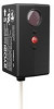
A - Safety sensor (capteur de sécurité, sensor de seguridad)
A - Wire terminal (door sensor) [cosse (capteur de porte), terminal del cable (sensor de la puerta)]
B - Wires (striped) [fils (rayés), cables (a rayas)]
C - Wires (plain) [fils (uni), cables (liso)]
D - Wire terminal marked with “W” (cosse marquée d’un « W », terminal de cable marcado con la
“W”)
E - Wire terminal marked with “G” (cosse marquée d’un « G », terminal de cable marcado con la “G”)
A - Garage door opener (d’ouvre-porte de garage, abridor de garaje de puerta)
B - Insulated staples (agrafes isolant, grapas aislado)
C - Safety sensors (capteurs de sécurité, sensors de seguridad)
D - Wire (fil, cable)
A - Safety sensor (capteur de sécurité, sensor
de seguridad)
B - Bracket (support, soporte)
C - Stud (montant, perno)
D - Long slot (fente longue, ranura largo)
E - Wing nut (écrou à oreilles, tuerca de
mariposa)
A - LED (green) [DEL (vert), LED (verde)]
B - Safety sensor (receiver) [capteur de sécurité (récepteur), sensor de seguridad (receptora)]
C - LED (red) [DEL (rouge), LED (rojo)]
D - Arrow (flèche, flecha)
E - Safety sensor (source) [capteur de sécurité (target), sensor de seguridad (fuente)]
A - Safety sensor (capteur de sécurité, sensor de
seguridad)
B - Lag bolt (tire-fond, tirafondo)
INSTALLATION
PACKING LIST
Safety Sensor (2), Wing Nut (2), Bracket (2), Lag Bolt (2), 2 in. Nails (2), Insulated
Staples, and Operator’s Manual.
INSTALLING THE SAFETY SENSORS
See Figures 1 - 6.
WARNING:
Always wear eye protection with side shields marked to comply with ANSI Z87.1
when assembling and performing maintenance on this product. Failure to do so
could result in objects being thrown into your eyes resulting in possible serious
injury.
A
991000838
2-13-18 (REV:03)
C
B
D
E
ONE WORLD TECHNOLOGIES, INC.
1428 Pearman Dairy Road, Anderson, SC 29625
Phone 1-877-205-5714
États-Unis, Téléphone 1-877-205-5714
USA, Teléfono 1-877-205-5714
www.ryobitools.com