Ryobi RY41135 Operation Manual 4
Ryobi RY41135 Manual
 |
View all Ryobi RY41135 manuals
Add to My Manuals
Save this manual to your list of manuals |
Ryobi RY41135 manual content summary:
- Ryobi RY41135 | Operation Manual 4 - Page 1
, Black Nut, Black Line Guide, White Line Guide, 0.095 in. Line (16 ft.), Locking Pin, SPEED WINDER, and Operator's Manual INSTALLING TRIMMER HEAD See Figures 1 - 6. The REEL-EASY Trimmer Head installs differently on different string trimmer attachments. Assembly instructions will vary based on the - Ryobi RY41135 | Operation Manual 4 - Page 2
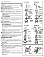
upper housing then twist upper housing onto the attachment (see figure 6). For curved shaft models, both sides of the housing. NOTE: If replacing trimmer line, do not insert more than 18 ft. manually advance the line. CURVED SHAFT STRAIGHT SHAFT ARBOR SPACER UPPER HOUSING SPRING WHITE LINE GUIDE - Ryobi RY41135 | Operation Manual 4 - Page 3
noir, écrou argentée, écrou noir, guide de ligne noir, guide de ligne blanc, 16 pi ligne de instructions correspondant au style et au type de votre support de fixation. NOTE : Si vous ne parvenez pas à identifier le style et le type de support de fixation que vous avez, communiquez avec le service - Ryobi RY41135 | Operation Manual 4 - Page 4
boîtier supérieur puis tournez la section du boîtier supérieur sur le support de fixation (voir la figure 6). Insérez le écrou argenté et tournez ÉPAULEMENT BOÎTIER SUPÉRIEUR ÉCROU NOIR RESSORT GUIDE DE LIGNE NOIR BOBINE BOUTON BOÎTIER INFÉRIEUR GUIDE DE LIGNE NOIR BOBINE BOUTON BOÎTIER INFÉRIEUR - Ryobi RY41135 | Operation Manual 4 - Page 5
, tuerca negro, guía de hilo negra, guía de hilo blanca, 16 pies (5,5 m) de hilo de 2,4 mm (0,095 pulg.), pasador de fijación, SPEED WINDER y manual del operador INSTALACIÓN DE CABEZAL DE LA RECORTADORA Vea las figuras 1 a 6. El cabezal de la recortadora REEL-EASY se instala de forma distinta en - Ryobi RY41135 | Operation Manual 4 - Page 6
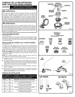
ón superior y empuje hacia abajo. Instale la guía de línea negra en el carrete. NOTA: Al realizar la instalación, alinee las muescas ubicadas en la parte inferior de la guía con los orificios correspondientes en el carrete. Alinee la nervadura de la perilla con las ranuras del carrete y coloque la
-
 1
1 -
 2
2 -
 3
3 -
 4
4 -
 5
5 -
 6
6
 |
 |
REEL-EASY TRIMMER HEAD
WITH SPEED WINDER
AC04156
WARNING:
To reduce the risk of injury, user must read and understand the
operator’s manual for their string trimmer before using this accessory.
Always wear eye protection with side shields marked to comply
with Z87.1 along with hearing protection. Ensure compatibility and
proper fit before using this accessory. Stop the string trimmer and
remove battery pack or disconnect spark plug wire before changing
or adjusting accessories.
WARNING:
Do not use this accessory if a part is damaged or missing. If you are
not comfortable performing any of the functions described in these
instructions, take your unit to an authorized service center. Use of a
trimmer head that has been improperly assembled could cause the
trimmer head to come apart and/or detach from your trimmer and
result in serious personal injury and/or property damage.
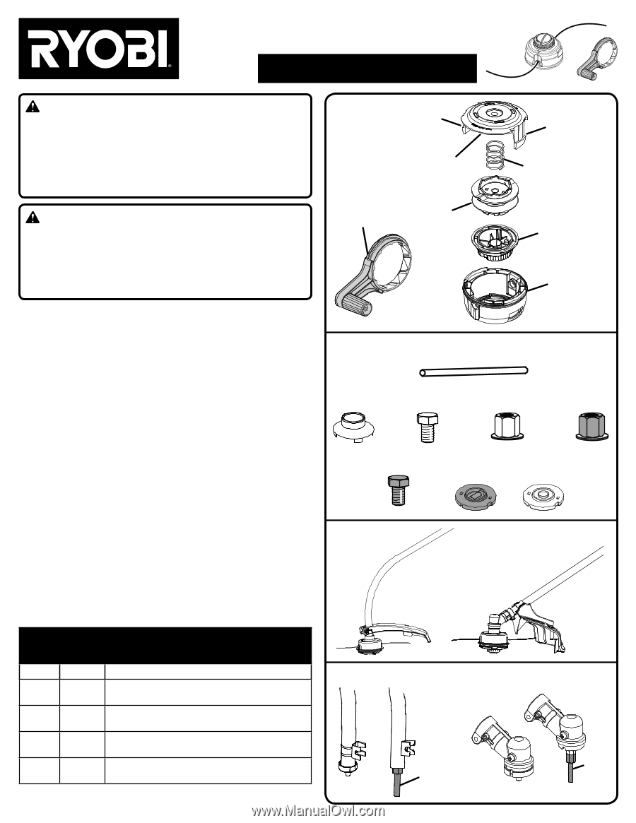
PACKING LIST
See Figures 1 - 2.
Trimmer Head Assembly, Spacer, Silver Bolt, Black Bolt, Silver Nut, Black
Nut, Black Line Guide, White Line Guide, 0.095 in. Line (16 ft.), Locking
Pin, SPEED WINDER, and Operator’s Manual
INSTALLING TRIMMER HEAD
See Figures 1 - 6.
The REEL-EASY Trimmer Head installs differently on different string
trimmer attachments. Assembly instructions will vary based on the style
and type of attachment you have. See figures 3 and 4 to determine if you
have a curved shaft or straight shaft attachment and if your attachment
comes with or without an arbor. Refer to the
Installation Chart
to
determine the appropriate items for your attachment. Be sure to follow
the instructions for your attachment style and type.
NOTE:
If you cannot identify the style and type of attachment you have,
contact customer service for assistance.
Stop the unit and remove battery pack or disconnect spark plug wire.
Open the REEL-EASY Trimmer Head assembly by depressing the tabs
on each side. The contents of the trimmer head are spring loaded,
so keep your other hand over the lower housing while depressing
the tabs.
Seperate the upper housing, spring, spool, knob, from lower housing
and set aside.
Locate the bolt, nut, line guide, and/or spacer required to install the
trimmer head to your attachment. Refer to the
Installation Chart
for
details.
INSTALLATION CHART
If the trimmer head does not fit with any of the adaptors or
hardware
supplied, contact Customer Service at 1-800-860-4050
for assistance.
Style
Type
Items Needed for Installation
Curved
Shaft
With
Arbor
Spacer, White Line Guide, Black Bolt,
and Trimmer Head Assembly
Curved
Shaft
Without
Arbor
Silver Nut, Black Line Guide,
and Trimmer Head Assembly
Straight
Shaft
With
Arbor
Spacer, White Line Guide, Silver Bolt,
and Trimmer Head Assembly
Straight
Shaft
Without
Arbor
Black Nut, Black Line Guide,
and Trimmer Head Assembly
Fig. 3
Fig. 4
Fig. 1
Fig. 2
STRAIGHT
SHAFT
UPPER
HOUSING
LOWER
HOUSING
SILVER
BOLT
SILVER
NUT
LOCKING
PIN
BLACK
NUT
BLACK
BOLT
BLACK
LINE GUIDE
WHITE
LINE GUIDE
CURVED
SHAFT
CURVED SHAFTS
STRAIGHT SHAFTS
ARBOR
ARBOR
SPRING
SPACER
TAB
TAB
SPOOL
KNOB
995000139
12-7-18 (REV:04)
Installation video available at
SPEED
WINDER