Ryobi TS1141L Operation Manual
Ryobi TS1141L Manual
 |
View all Ryobi TS1141L manuals
Add to My Manuals
Save this manual to your list of manuals |
Ryobi TS1141L manual content summary:
- Ryobi TS1141L | Operation Manual - Page 1
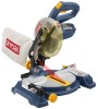
OPERATOR'S MANUAL 7-1/4 in. Compound Miter Saw TS1141 - Double Insulated Your miter saw has been engineered and manufactured to our high standard for dependability, ease of operation, and operator safety. When properly cared for, it will give you years of rugged, trouble-free performance. this - Ryobi TS1141L | Operation Manual - Page 2
Loose Parts List...12 Assembly...13-21 Operation...22-28 Adjustments...29-30 Maintenance...31 Parts Ordering / Service...Back Page COVERS: This warranty covers all defects in workmanship or materials in your RYOBI® power tool for a period of two years from the date of purchase - Ryobi TS1141L | Operation Manual - Page 3
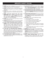
manual for recommended accessories. The use of improper accessories may result in injury. NEVER STAND ON or other part that is damaged must be properly repaired or replaced by an authorized service center to READ ALL INSTRUCTIONS KNOW YOUR POWER TOOL. Read the operator's manual carefully. - Ryobi TS1141L | Operation Manual - Page 4
, or any medication. When servicing use only identical replacement parts. Use of any other parts may create a hazard or cause MITER TABLE AND SAW ARM (BEVEL FUNCTION) ARE LOCKED IN POSITION BEFORE OPERATING THE SAW. Lock the miter table by securely tightening the miter lock lever. Lock the saw - Ryobi TS1141L | Operation Manual - Page 5
not secured to a work surface. ALWAYS secure this saw to a stable work surface before any use to avoid serious personal injury. AVOID direct eye exposure when using the laser guide. SAVE THESE INSTRUCTIONS. Refer to them frequently and use to instruct other users. If you loan someone this tool - Ryobi TS1141L | Operation Manual - Page 6
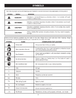
and learn their meaning. Proper interpretation of these symbols will allow you to operate the tool better and safer. SYMBOL NAME Safety Alert Read Operator's Manual DESIGNATION/EXPLANATION Precautions that involve your safety. To reduce the risk of injury, user must read and understand operator - Ryobi TS1141L | Operation Manual - Page 7
Only round jacketed cords listed by Underwriter's Laboratories service technician. For service, we suggest you return the tool to your nearest authorized service center for repair. Always use original factory replacement parts when servicing Used on 12 gauge - 20 amp circuit NOTE: AWG = American - Ryobi TS1141L | Operation Manual - Page 8
saw during a ripping operation. Arbor The shaft on which a blade or cutting tool is mounted. Bevel Cut A cutting operation made with the blade at any angle other than 90° to the table surface. Compound Cut A cross cut made with both a miter guided by a fence, miter gauge supported. Through Sawing - Ryobi TS1141L | Operation Manual - Page 9
Lock lever "D" handle switch lock Upper Blade Guard Dust BAG BLADE WRENCH laser guide Switch Trigger Lower blade guard Bevel Lock Knob Bevel Scale "NO HANDS ZONE" BOUNDARY LINE "NO HANDS ZONE" LABEL bevel scale miter fence Miter Scale throat plate MITER TABLE WORK CLAMP base Fig. 1 9 - Ryobi TS1141L | Operation Manual - Page 10
the switch is released. LASER GUIDE For more accurate cuts, a laser guide is included with your miter saw. When used properly, the laser guide makes accurate, precision cutting simple and easy. Spindle Lock Button Fig. 3 MITER FENCE The miter fence on the compound miter saw has been provided to - Ryobi TS1141L | Operation Manual - Page 11
will not start until you depress the switch lock with your thumb then squeeze the switch trigger. To prevent unauthorized use of the compound miter saw, disconnect it from the power supply and lock the switch in the off position. To lock the switch, install a padlock (not included) through the hole - Ryobi TS1141L | Operation Manual - Page 12
LOOSE PARTS LIST The following items are included with your compound miter saw: Miter Saw Base Blade Wrench Miter Saw Head AAA Batteries (2) Dust Bag Rear Bracket/Carrying Handle Work Clamp Bevel Knob Blade Bevel Indicator and Screw Operator's Manual miter saw base - Ryobi TS1141L | Operation Manual - Page 13
settings, refer to specific procedures explained in this manual. If any parts are damaged or missing, please call 1-800-525-2579 for assistance. WARNING: Do not start the compound miter saw without checking for interference between the blade and the miter fence. Damage could result to the blade - Ryobi TS1141L | Operation Manual - Page 14
: Always make sure the compound miter saw is securely mounted to a workbench or an approved workstand. Failure to heed this warning can result in serious personal injury. Mounting Holes See Figure 9. If not using a stand, the saw should be mounted to a firm supporting surface such as a workbench - Ryobi TS1141L | Operation Manual - Page 15
the next section to install the Dust Bag. To determine if your saw was factory assembled, see UNPACKING. Secure the base to the stand or other firm supporting surface such as a workbench. Remove the paper seal from the miter saw head. Remove the tape securing the bolt from the back of the - Ryobi TS1141L | Operation Manual - Page 16
fence or the table. It also prevents the workpiece from creeping toward the saw blade. This is very helpful when cutting compound miters. Depending on either hole on the saw table base. Rotate the knob on the work clamp to move it in or out as needed. INSTALLing BATTERIES IN LASER See Figure 14. - Ryobi TS1141L | Operation Manual - Page 17
performance of procedures other than those specified herein may result in hazardous radiation exposure. aligning the laser guide line See Figure 15. Unplug the saw. Draw a line on the workpiece. When the laser guide switch is turned on it will generate a red line on the work surface. This line will - Ryobi TS1141L | Operation Manual - Page 18
securing the blade on the spindle. Either of these situations could result in a serious accident and can cause serious personal injury. Unplug the saw. Raise the saw arm. Rotate lower blade guard up and remove blade bolt cover screw. Rotate blade bolt cover up and back to expose the blade - Ryobi TS1141L | Operation Manual - Page 19
in this manual show only portions of the compound miter saw. This is intentional so that we can clearly show points being made in the illustrations. Never operate the saw without all guards securely in place and in good operating condition. MITER TABLE Miter lock lever MITER FENCE Square - Ryobi TS1141L | Operation Manual - Page 20
the pointer aligns with zero on the miter scale. Push the miter lock lever down to lock the miter table. Lay a square flat on the miter table. Place one leg of the square against the fence. Slide the other leg of the square against the flat part of saw blade. Note: Make sure that the square - Ryobi TS1141L | Operation Manual - Page 21
knob. Place a square against the miter table and the flat part of saw blade. Note: Make sure that the square contacts the flat part of the saw blade, not the blade teeth. square MITER TABLE blade BEVEL LOCK KNOB MITER FENCE CORRECT VIEW OF Blade SQUARE WITH Miter Table Fig. 26 BEVEL LOCK KNOB - Ryobi TS1141L | Operation Manual - Page 22
out the lock pin and lift saw arm to its full height. Lift the miter lock lever. Rotate the miter table until the pointer aligns with zero on the miter scale. CROSS CUT WARNING: Before starting any cutting operation, clamp or bolt the compound miter saw to a workbench or an approved workstand - Ryobi TS1141L | Operation Manual - Page 23
support the opposite end of the stock with a roller stand or with a work surface level with the saw table. See Figure 35. Align cutting line on workpiece with edge of saw from turning before removing the workpiece from the miter table. INDICATOR POINT miter CUT WORK CLAMP Fig. 30 BEVEL SCALE TO - Ryobi TS1141L | Operation Manual - Page 24
or molding, support the opposite end of the stock with a roller stand or with a work surface level with the saw table. See Figure 35 miter table must be rotated to the correct angle and the saw arm must be tilted to the correct bevel angle. Care should always be taken when making compound miter - Ryobi TS1141L | Operation Manual - Page 25
the switch trigger and allow the saw blade to stop rotating before raising the blade out of the workpiece. Wait until the electric brake stops blade from turning before removing the workpiece from miter table. 45° x 45° COMPOUND MITER CUT Fig. 34 to SUPPORT LONG WORKPIECES See Figure 35. Long - Ryobi TS1141L | Operation Manual - Page 26
OPERATION CUTTING COMPOUND MITERS To aid in making the correct settings, the compound angle setting chart below has been provided. Since compound cuts are the most difficult to accurately obtain, trial cuts should be made in scrap material, and much thought and planning made, prior to making - Ryobi TS1141L | Operation Manual - Page 27
. All Standard (U.S.) crown molding with 52° and 38° angles. The crown molding is placed flat on the miter table using the compound features of the miter saw. Laying molding flat on the miter table See Figure 36. To use this method for accurately cutting crown molding for a 90° inside or outside - Ryobi TS1141L | Operation Manual - Page 28
° 33.85° 33.85° 33.85° cutting warped material See Figures 37 - 38. When cutting warped material, always make sure it is positioned on the miter table with the convex side against the fence as shown in figure 37. If the warped material is positioned the wrong way as shown in figure - Ryobi TS1141L | Operation Manual - Page 29
raise by itself or if there is play in the pivot joints, have saw repaired by at your nearest authorized service center. Bevel Pivot Adjustment The compound miter saw should bevel easily by loosening the bevel lock knob and tilting the saw arm to the left. If movement is tight or if there is - Ryobi TS1141L | Operation Manual - Page 30
procedures other than those specified herein may result in hazardous radiation exposure. TO ADJUST THE LASER GUIDE See Figure 40. Use the work clamp or a C-clamp to secure a piece of scrap wood. Plug the saw into the power source and make a slight cut to score the wood. Release the switch - Ryobi TS1141L | Operation Manual - Page 31
servicing, use only identical replacement parts. Use of any other parts used on fiberglass material, wallboard, spackling compounds, or plaster are subject to accelerated compressed air. Brush REPLACEMENT See Figure 42. The saw has externally accessible brush assemblies that should be periodically - Ryobi TS1141L | Operation Manual - Page 32
'S MANUAL 7-1/4 in. Compound Miter Saw TS1141 - Double Insulated WARNING: Some dust created by power sanding, sawing, grinding Authorized Service Center. You can also check our web site at www.ryobitools.com for a complete list of Authorized Service Centers. • MODEL NO. AND SERIAL NO. The model
-
 1
1 -
 2
2 -
 3
3 -
 4
4 -
 5
5 -
 6
6 -
 7
7 -
8
-
9
-
10
-
11
-
12
-
13
-
14
-
15
-
16
-
17
-
18
-
19
-
20
-
21
-
22
-
23
-
24
-
25
-
26
-
27
-
28
-
29
-
30
-
31
-
32
 |
 |

SAVE THIS MANUAL FOR FUTURE REFERENCE
Your miter saw has been engineered and manufactured to our high standard for dependability, ease of operation, and
operator safety. When properly cared for, it will give you years of rugged, trouble-free performance.
WARNING:
To reduce the risk of injury, the user must read and understand the operator’s manual before using
this product.
Thank you for your purchase.
OPERATOR’S MANUAL
7-1/4 in. Compound Miter Saw
TS1141 - Double Insulated