Ryobi TSS101L English Manual
Ryobi TSS101L Manual
 |
View all Ryobi TSS101L manuals
Add to My Manuals
Save this manual to your list of manuals |
Ryobi TSS101L manual content summary:
- Ryobi TSS101L | English Manual - Page 1
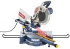
OPERATOR'S MANUAL 10 in. SLIDING COMPOUND MITER SAW with Laser TSS100L Your miter saw has been engineered and manufactured to our high standard for dependability, ease of operation, and operator safety. When properly cared for, it will give you years of rugged, trouble-free performance. WARNING: To - Ryobi TSS101L | English Manual - Page 2
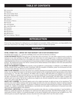
Safety Rules...4-5 Symbols...6-7 Electrical...8 Glossary of Terms...9 Features...10-12 Tools Needed...12 Loose Parts List...13 Assembly...14-21 Operation...22-31 Adjustments...32-33 Maintenance...34 Parts Ordering / Service...36 INTRODUCTION This tool has many features for - Ryobi TSS101L | English Manual - Page 3
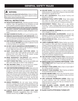
WITH CARE. Keep tools sharp and clean for better and safer performance. Follow instructions for lubricating and changing accessories. DISCONNECT TOOLS. When not in use, before servicing, or when changing attachments, blades, bits, cutters, etc., all tools should be disconnected from power source - Ryobi TSS101L | English Manual - Page 4
. When servicing use only identical replacement parts. Use of any other parts may create a hazard or cause product damage. Use only recommended accessories listed in this manual or addendums. Use of accessories that are not listed may cause the risk of personal injury. Instructions for safe use - Ryobi TSS101L | English Manual - Page 5
CUTS by pushing the saw blade down on top of the workpiece then sliding it back toward the rear of the saw. DO NOT pull the saw toward you while making a cut. ALWAYS carry the tool only by the carrying handle. AVOID direct eye exposure when using the laser guide. This saw can tip over if - Ryobi TSS101L | English Manual - Page 6
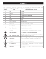
's manual before using this product. Always wear safety goggles or safety glasses with side shields and, as necessary, a full face shield when operating this product. Safety Alert No Hands Symbol Hot Surface Precautions that involve your safety. Failure to keep your hands away from the blade will - Ryobi TSS101L | English Manual - Page 7
CENTER for repair. When servicing, use only identical replacement parts. WARNING: To avoid serious personal injury, do not attempt to use this product until you read thoroughly and understand completely the operator's manual. If you do not understand the warnings and instructions in the operator - Ryobi TSS101L | English Manual - Page 8
listed 10 - **Used on 12 gauge - 20 amp circuit support one power tool may not be able to support two or three tools. Grounding Instructions service personnel if the grounding instructions are not completely understood, or if in doubt as to whether the tool is properly grounded. Repair or replace - Ryobi TSS101L | English Manual - Page 9
. Bevel Cut A cutting operation made with the blade at any angle other than 90° to the table surface. Chamfer A cut removing a wedge from a block so the end (or part of the end) is angled rather than at 90°. Compound Cut A cross cut made with both a miter and a bevel angle. Cross Cut A cutting or - Ryobi TSS101L | English Manual - Page 10
upper blade guard Bevel Scale "D" HANDLE Switch Trigger Dust bag slide bar work shaft knob work clamp MITER FENCE lower blade guard "NO HANDS ZONE" BOUNDARY LINE "NO HANDS ZONE" LABEL throat plate TABLE EXTENSION base MITER TABLE Miter Scale CONTROL ARM support foot 10 Miter Lock Handle - Ryobi TSS101L | English Manual - Page 11
laser guide makes accurate, precision cutting simple and easy. MITER FENCE The miter fence on the compound miter saw has been provided to hold your workpiece securely against when making all cuts. The left side is larger providing additional support. MITER LOCK HANDLE See Figure 2. The miter lock - Ryobi TSS101L | English Manual - Page 12
sliding feature of this tool. SPINDLE LOCK BUTTON See Figure 4. The spindle lock button locks the spindle and stops the blade from rotating. Depress and hold the lock button while installing, changing, or removing blade. SWITCH TRIGGER See Figure 5. To prevent unauthorized use of the compound miter - Ryobi TSS101L | English Manual - Page 13
LOOSE PARTS LIST The following items are included with your Compound Miter Saw: Dust Bag Work Clamp Clamp Brackets (2) Blade Wrench Clamp Bracket Screws (2) Table Extensions (2) Blade Operator's Manual blade wrench DUST BAG TABLE EXTENSION WORK CLAMP TABLE EXTENSION CLAMP - Ryobi TSS101L | English Manual - Page 14
serious personal injury. The compound miter saw should be mounted to a firm supporting surface such as a workbench. Four bolt holes have been provided in the saw base for this purpose. Each of the four mounting holes should be bolted securely using 3/8 in. machine bolts, lock washers, and hex nuts - Ryobi TSS101L | English Manual - Page 15
handle and apply downward pressure while at the same time pulling the lock pin out and away from the saw housing. Release the lock pin allowing it to lock the saw into place. DUST BAG See Figure 10. A dust bag is provided for use on this miter saw. It fits over the exhaust port on the upper blade - Ryobi TSS101L | English Manual - Page 16
The work clamp provides greater control by clamping the workpiece to the fence or the saw table. It also prevents the workpiece from creeping toward the saw blade. This is very helpful when cutting compound miters. Depending on the cutting operation and the size of the workpiece, it may be necessary - Ryobi TSS101L | English Manual - Page 17
Install / replace the Blade See Figures 14 - 15. Spindle Lock Button WARNING: A 10 in. blade is the maximum blade capacity of the saw. Never use a blade that is too thick to allow outer blade washer to engage with the flats on the spindle. Larger blades will come in contact with the blade guards - Ryobi TSS101L | English Manual - Page 18
the spindle lock button is not engaged before reconnecting saw into power source. Never engage spindle lock button when blade is rotating. Danger: Laser in order to leave the mark. After you have become familiar with using the laser guide, you will be able to remove, cut, or leave your mark on the - Ryobi TSS101L | English Manual - Page 19
Never operate the saw without a throat plate installed. To remove / replace: Unplug the saw. Remove saw base. Retighten the screws, being careful not to overtighten which can cause the throat plate to bow or bend. ADJUSTING SUPPORT FOOT See Figure 17. When making sliding cuts, turn the support - Ryobi TSS101L | English Manual - Page 20
tighten the miter lock handle. Lay a framing square flat on the miter table. Place one leg of the square against the fence. Slide the other leg of the square against the flat part of saw blade. Note: Make sure that the square contacts the flat part of the saw blade, not the blade teeth. The - Ryobi TSS101L | English Manual - Page 21
the miter lock handle. Loosen the bevel lock lever and set saw arm at 0° bevel (blade set 90° to miter table). Tighten bevel lock lever. Place a combination square against the miter table and the flat part of saw blade. Note: Make sure that the square contacts the flat part of the saw blade, not - Ryobi TSS101L | English Manual - Page 22
but for fine joinery cuts or cutting plastic, use one of the accessory blades available from the Ryobi dealer. WARNING: Before starting any cutting operation, clamp or bolt the compound miter saw to a workbench. Never operate the miter saw on the floor or in a crouched position. Failure to heed this - Ryobi TSS101L | English Manual - Page 23
run of the cutting operation to make sure that no problems will occur when the cut is made. Grasp the saw handle firmly. Squeeze the switch trigger. Allow several seconds for the blade to reach maximum speed. Slowly lower the blade into and through the workpiece. Release the switch trigger and - Ryobi TSS101L | English Manual - Page 24
. A straight bevel cut is made with the miter table set at the zero degree position and the blade set at an angle between 0° and 45°. Pull out the lock pin and lift saw arm to its full height. Loosen the miter lock handle. Rotate the miter lock handle approximately one-half turn to the left to - Ryobi TSS101L | English Manual - Page 25
long pieces of lumber or molding, support the opposite end of the stock with a roller stand or with a work surface level with the saw table. See Figure 32. Compound Miter Cut C-CLAMP Fig. 30 Align the cutting line on the workpiece with the edge of saw blade. Grasp the stock firmly with one - Ryobi TSS101L | English Manual - Page 26
placed along the workpiece so it does not sag. The support should let the workpiece lay flat on the base of the saw and work table during the cutting operation. Use the optional work clamp or a C-clamp to secure the workpiece. 45° x 45° COMPOUND MITER CUT Fig. 31 0 Long 0 workpiece Workpiece - Ryobi TSS101L | English Manual - Page 27
cutting long pieces of lumber or molding, support the opposite end of the stock with a roller stand or with a work surface level with the saw table. See Figure 32. Align the cutting line on the workpiece with the edge of saw blade. Loosen the slide lock knob by turning the knob counterclockwise - Ryobi TSS101L | English Manual - Page 28
MUST be removed. To attach the auxiliary fence to the saw: Place the wood against the miter fence and mark the hole location from behind the fence using miter fence using flat head screws. With the miter table set at 0°, make a complete cut through the auxiliary fence to create the blade slot - Ryobi TSS101L | English Manual - Page 29
COMPOUND MITERS To aid in making the correct settings, the compound angle setting chart below has been provided. Since compound B- 18.75° M- 22.21° B- 20.70° M- 20.36° B- 22.52° M- 18.32° B- 24.18° M- 16.10° B- 25.66° M- 13.71° B- 26.95° M- 11.17° B- 28.02° 7 M- 25.71° B- 0.00° M- 25.63° B- 2.17° M- - Ryobi TSS101L | English Manual - Page 30
miter table and against the fence. When setting the bevel and miter angles for compound miters, remember that the settings are interdependent; changing one angle changes crown molding is placed flat on the miter table using the compound features of your miter saw. Bevel Angle Setting 33.85° 33.85 - Ryobi TSS101L | English Manual - Page 31
When cutting warped material, always make sure it is positioned on the miter table with the convex side against the fence as shown in figure material is positioned the wrong way as shown in figure 38, it will pinch the blade near the completion of the cut. Right WRONG Fig. 38 Fig. 37 WARNING: - Ryobi TSS101L | English Manual - Page 32
could result in serious personal injury. The compound miter saw has been adjusted at the factory for making saw. Turn the hex nut with the blade wrench. Once all adjustments have been made, lift the bevel lock lever to relock the bevel. Recheck and readjust as needed. TO ADJUST THE LASER GUIDE - Ryobi TSS101L | English Manual - Page 33
in the Assembly section of this manual. Retighten bevel lock lever. Next, retighten lock nut securing the positive stop adjustment screw. Recheck blade-to-table alignment. Note: The above procedure can be used to check blade squareness of the saw blade to the miter table at both 0° and 45° angles - Ryobi TSS101L | English Manual - Page 34
servicing, use only identical replacement parts. Use of any other parts may used on fiberglass material, wallboard, spackling compounds, or plaster are subject to accelerated wear further lubrication is required. Brush REPLACEMENT See Figure 43. The saw has externally accessible brush assemblies - Ryobi TSS101L | English Manual - Page 35
NOTES 35 - Ryobi TSS101L | English Manual - Page 36
OPERATOR'S MANUAL 10 in. SLIDING COMPOUND MITER SAW with Laser TSS100L WARNING: Some dust created by power sanding, sawing, grinding, drilling, and other construction activities contains chemicals known to cause cancer, birth defects or other reproductive harm. Some examples of these chemicals are:
-
 1
1 -
 2
2 -
 3
3 -
 4
4 -
 5
5 -
 6
6 -
 7
7 -
8
-
9
-
10
-
11
-
12
-
13
-
14
-
15
-
16
-
17
-
18
-
19
-
20
-
21
-
22
-
23
-
24
-
25
-
26
-
27
-
28
-
29
-
30
-
31
-
32
-
33
-
34
-
35
-
36
 |
 |
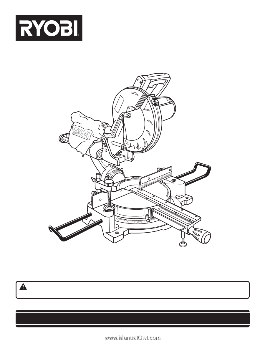
SAVE THIS MANUAL FOR FUTURE REFERENCE
Your miter saw has been engineered and manufactured to our high standard for dependability, ease of operation, and
operator safety. When properly cared for, it will give you years of rugged, trouble-free performance.
WARNING:
To reduce the risk of injury, the user must read and understand the operator’s manual before using
this product.
Thank you for purchase.
OPERATOR’S MANUAL
10 in. SLIDING COMPOUND MITER SAW
WITH LASER
TSS100L