Samsung DV209AEW User Manual (user Manual) (ver.1.0) (English) - Page 15
U.s. Models - reviews
 |
View all Samsung DV209AEW manuals
Add to My Manuals
Save this manual to your list of manuals |
Page 15 highlights
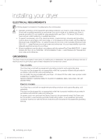
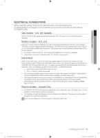
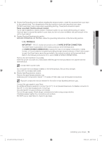
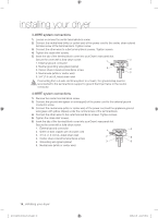
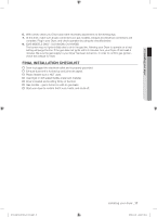
01 installing your dryer 4. Review the Exhausting section before installing the exhaust system. Install the ductwork from your dryer to the exhaust hood. The crimped end of the duct sections must point away from your dryer. DO NOT use sheet metal screws when assembling ducting. These joints should be taped. Never use plastic flexible exhaust material. Tip for tight installations: install a section of exhaust system to your dryer before putting it in place. Use duct tape to secure this section to your dryer, but do not cover ventilation slots at the back of the unit in dryer cabinet. 5. Review Electrical Requirements section. BEFORE OPERATING OR TESTING, follow the grounding instructions in the Grounding section. U.S. MODELS: IMPORTANT - All U.S. models are produced for a 3-WIRE SYSTEM CONNECTION. The Dryer frame is grounded to the neutral conductor at the terminal block. A 4-WIRE SYSTEM CONNECTION is required for new or remodeled construction, mobile homes, or if local codes do not permit grounding through neutral conductor. If the 4-wire system is used, the Dryer frame cannot be grounded to the neutral conductor at the terminal block. Refer to the following instructions for 3- and 4-WIRE SYSTEM CONNECTIONS. Remove the terminal block cover plate. Insert the power cord with a UL-listed strain relief through the hole provided in the cabinet near the terminal block. A strain relief must be used. Do not loosen the nuts already installed on the terminal block. Be sure they are tight. Use a 3/8" (1cm) deep well socket. 6. Review Gas Requirements section. Remove the pipe thread protective cap. Apply pipe joint compound or about 1 1/2 wraps of Teflon tape over all threaded connections. Pipe joint compound must be resistant to the action of any liquefied petroleum gas. Connect the gas supply to your Dryer. An additional fitting is required to connect the 3/4" (1.9 cm) female thread end of a flexible connector to the 3/8" (1 cm) male threaded end on the dryer. Securely tighten the gas line fitting over threads. Turn on the gas supply. Check all gas connections for leaks using a soap solution. If bubbles appear, tighten the connections and recheck. DO NOT use an open flame to check for gas leaks. DV218AEW-02568A-01_EN.indd 15 installing your dryer _15 2008-12-08 ¿ÀÀü 9:08:40
-
 1
1 -
2
-
3
-
4
-
5
-
6
-
7
-
8
-
9
-
 10
10 -
 11
11 -
 12
12 -
 13
13 -
 14
14 -
 15
15 -
 16
16 -
 17
17 -
 18
18 -
 19
19 -
 20
20 -
21
-
22
-
23
-
24
-
25
-
26
-
27
-
28
-
29
-
30
-
31
-
32
-
33
-
34
-
35
-
36
-
37
-
38
-
39
-
40
-
41
-
42
-
43
-
44
-
45
-
46
-
47
-
48
-
49
-
50
-
51
-
52
-
53
-
54
-
55
-
56
-
57
-
58
-
59
-
60
-
61
-
62
-
63
-
64
-
65
-
66
-
67
-
68
 |
 |