Samsung MM-ZJ6 Service Manual
Samsung MM-ZJ6 Manual
 |
View all Samsung MM-ZJ6 manuals
Add to My Manuals
Save this manual to your list of manuals |
Samsung MM-ZJ6 manual content summary:
- Samsung MM-ZJ6 | Service Manual - Page 1
MICRO COMPONENT SYSTEM MM-ZJ6 SERVICE Manual MICRO COMPONENT SYSTEM CONTENTS 1. Alignment and Adjustments 2. Exploded Views and Parts List 3. Electrical Parts List 4. Block Diagrams 5. Wiring Diagram 6. Schematic Diagrams - Confidential - - Samsung MM-ZJ6 | Service Manual - Page 2
ELECTRONICS © Samsung Electronics Co.,Ltd. FEB. 2004 Printed in Korea Code no. AH68-01383X - Samsung MM-ZJ6 | Service Manual - Page 3
594 KHz MA Maximum Output(Fig1-4) LW OSC Adjustment LW RF Adjustment 146~290 KHz LO 150 KHz LA 2~7.0±0.5V Maximum Output(Fig1-4) Samsung Electronics Fig 1-4 OSC Voltage FM THD Adjustment SSG FREQ. Adjustment point (FM DET) Output 98 MHz FD 60 dB Minumum Distortion (0.4% below) (Figure - Samsung MM-ZJ6 | Service Manual - Page 4
- 5512 into Deck 2 1) Press REC PLAY button. 2) TAPE PCB JCW3 ,connected - Turn JSR2L,JSR2R to the right and left to VTVM CHECK TO 7mV(±0.5mV) 1-2 Samsung Electronics - Samsung MM-ZJ6 | Service Manual - Page 5
FF19S-31 F765-292 F514-129 CCM09-120L2-6 SG-107F3;KODENSHI SPLFF SPLFE1 Remarks A/STOP F513-853 FF19S-31 F765-292 F514-129 Samsung Electronics No. Code No. AH59-01267A 1 AH81-00543A 2 AH81-00733A 3 AH81-00543C 4 AH81-00543D 5 AH81-00543E 6 AH81-00543F 7 AH81-01356A 8 AH81-00543H - Samsung MM-ZJ6 | Service Manual - Page 6
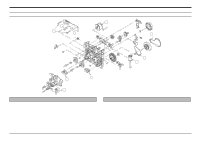
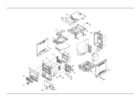
2-2 Total Exploded View and Parts List 2-2 Samsung Electronics - Samsung MM-ZJ6 | Service Manual - Page 7
* Parts List of The Exploded View Samsung Electronics 2-3 - Samsung MM-ZJ6 | Service Manual - Page 8
2-3 SPEAKER Exploded View and Parts list * CAUTION : It is used the bonding, connect FRONT PANEL to CABINET WOODEN. So when the disassembly, take extreme care not to damage the SPEAKER. 2-4 Samsung Electronics - Samsung MM-ZJ6 | Service Manual - Page 9
) CIS(NO RDS) LW BAND SW BAND AH59-01159J REMOCON-ASSY;MM-ZJ6,SAMSUNG,-,-,27KEY,-,- AH59-01293A DECK;CMS300-V,G4HI-1CD TOP,-,-,-,-, LSW1 3409-001078 0ohm,5%,1/4W,TP,3216 R-CHIP;0ohm,5%,1/4W,TP,3216 Samsung Electronics *S.N.A. : Service Not Available Location no. Code no. Description & - Samsung MM-ZJ6 | Service Manual - Page 10
0402-000127 0402-000127 0402-000127 0402-000127 0402-000127 0501-000398 0903-001273 2001-000241 ASSY PCB;MM-ZJ6,FRONT DIODE-RECTIFIER;1N5402,200V,3A,DO-201AD, DIODE-RECTIFIER;1N5402,200V,3A,DO-201AD, DIODE-RECTIFIER ;1NF,10%,50V,Y5P,TP,3 C-CERAMIC,MLC-AXIAL;1NF,10%,50V,Y5P,TP,3 Samsung Electronics - Samsung MM-ZJ6 | Service Manual - Page 11
30mohm FUSE-CLIP;250V,7.5A,30mohm PCB-FRONT;MM-ZJ6,FR1,1,-,1.6T,329.7*197, ASSY PCB-MAIN PCB ASSY;MM-J4,MAIN TR-POWER;-,PNP,25W,TO-220F ;1N4148,75V,150MA,DO-35,T DIODE-SWITCHING;1N4148,75V,150MA,DO-35,T Samsung Electronics Location no. Code no. Description & Specification AD15 AD2 AD20 RD1 RD10 - Samsung MM-ZJ6 | Service Manual - Page 12
,2mm C-AL;1uF,20%,50V,GP,BK,5x11mm,2mm C-AL;1uF,20%,50V,GP,BK,5x11mm,2mm C-AL;1uF,20%,50V,GP,BK,5x11mm,2mm Samsung Electronics - Samsung MM-ZJ6 | Service Manual - Page 13
;MM-J4/J6,FR1,1,-,1.6T,197*247, ASSY-CA'DECK;-,MMJ4/J6EUROOP,- CONNECT WIRE;MM-J6,-,-,6P,-,-,-,51004,-, DECK-CASSETTE;CMAL6Z212A,MM-J4,-,-,DC12V SCREW;-,-,L8,YEL,+,-,-,M2.6,-,HOLDER-DECK;MM-J4,ABS 94HB,-,-,-,-,- Remarks Location no. Code no. Description & Specification Remarks Samsung Electronics - Samsung MM-ZJ6 | Service Manual - Page 14
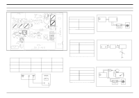
4. Block Diagram 4-1 CD Part Samsung Electronics 4-1 - Samsung MM-ZJ6 | Service Manual - Page 15
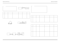
5. Wiring Diagram Samsung Electronics 5-1 - Samsung MM-ZJ6 | Service Manual - Page 16
6. Schematic Diagram 6-1 CD Part - This Document can not be used without Samsung's authorization - Samsung Electronics 6-1 - Samsung MM-ZJ6 | Service Manual - Page 17
6-2 MAIN - This Document can not be used without Samsung's authorization - 6-2 Samsung Electronics - Samsung MM-ZJ6 | Service Manual - Page 18
6-3 TUNER - This Document can not be used without Samsung's authorization - Samsung Electronics 6-3
-
 1
1 -
 2
2 -
 3
3 -
 4
4 -
 5
5 -
 6
6 -
 7
7 -
8
-
9
-
10
-
11
-
12
-
13
-
14
-
15
-
16
-
17
-
18
 |
 |
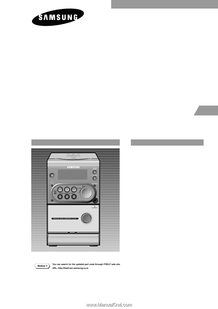
MICRO COMPONENT
SYSTEM
MM-ZJ6
SERVICE
Manual
MICRO COMPONENT SYSTEM
CONTENTS
1. Alignment and Adjustments
2. Exploded Views and Parts List
3. Electrical Parts List
4. Block Diagrams
5. Wiring Diagram
6. Schematic Diagrams
- Confidential -