Samsung MW1150WA Service Manual - Page 12
High Voltage Capacitor - microwave oven
 |
View all Samsung MW1150WA manuals
Add to My Manuals
Save this manual to your list of manuals |
Page 12 highlights
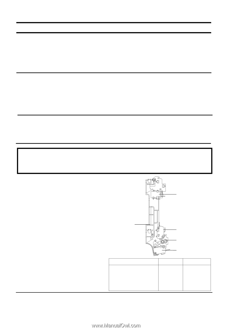
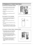
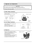
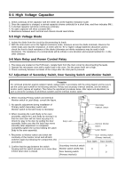
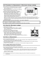
5-4 High Voltage Capacitor 1. Check continuity of the capacitor with the meter set at the highest resistance scale. 2. Once the capacitor is charged, a normal capacitor shows continuity for a short time, and then indicates 9M . 3. A shorted capacitor will show continuous continuity. 4. An open capacitor will show constant 9M . 5. Resistance between each terminal and chassis should read infinite. 5-5 High Voltage Diode 1. Isolate the diode from the circuit by disconnecting its leads. 2. With the ohm-meter set at the highest resistance scale, measure across the diode terminals. Reverse the meter leads and read the resistance. A meter with 6V, 9V or higher voltage batteries should be used to check the front-to back resistance of the diode (otherwise an infinite resistance may be read in both directions). The resistance of a normal diode will be infinite in one direction and several hundred K in the other direction. 5-6 Main Relay and Power Control Relay 1. The relays are located on the PCB Ass'y. Isolate them from the main circuit by disconnecting the leads. 2. Operate the microwave oven with a water load in the oven. Set the power level set to high. 3. Check continuity between terminals of the relays after the start pad is pressed. 5-7 Adjustment of Secondary Switch, Door Sensing Switch and Monitor Switch Precaution For continued protection against radiation hazard, replace parts in accordance with the wiring diagram and be sure to use the correct part number for the following switches: Primary and secondary interlock switches, and the interlock monitor switch (replace all together). Then follow the adjustment procedures below. After repair and adjustment, be sure to check the continuity of all interlock switches and the interlock monitor switch. 1. When mounting Primary switch and Interlock Monitor switch to Latch Body, consult the figure. 2. No specific adjustment during installation of Primary switch Secondary switch and Monitor switch to the latch body is necessary. Secondary Interlock Switch 3. When mounting the Latch Body to the oven assembly, adjust the Latch Body by moving it so that the oven door will not have any play in it. Check for play in the door by pulling the door assembly. Make sure that the latch keys move smoothly after adjustment is completed. Completely tighten the screws holding the Latch Body to the oven assembly. Body Latch Interlock Monitor Switch Lever Switch 4. Reconnect to Monitor switch and check the continuity of the monitor circuit and all latch switches again by following the components test procedures. 5. Confirm that the gap between the switch housing and the switch actuator is no more than 0.5mm when door is closed. Door Sensing Switch (Primary Interlock) Door Open Door Closed Secondary Interlock switch ∞ 0 Monitor switch (COM-NC) 0 ∞ Door Sensing switch ∞ 0 (Primary Interlock)
-
 1
1 -
2
-
3
-
4
-
5
-
6
-
 7
7 -
 8
8 -
 9
9 -
 10
10 -
 11
11 -
 12
12 -
 13
13 -
 14
14 -
 15
15 -
 16
16 -
 17
17 -
18
-
19
-
20
-
21
-
22
-
23
 |
 |