Samsung SCC-B2300 Service Manual
Samsung SCC-B2300 Manual
 |
View all Samsung SCC-B2300 manuals
Add to My Manuals
Save this manual to your list of manuals |
Samsung SCC-B2300 manual content summary:
- Samsung SCC-B2300 | Service Manual - Page 1
Power Supply Synchronization Method ˆ DAY/NIGHT CAMERA (SCC-B2391(P)/SCC-B2091P/SCC-B2300) SCC-B2391(P)/SCC-B2091P/SCC-1391(P)/SCC-B1091P/SCC-B2300 This Service Manual is a property of Samsung Electronics Co .,Ltd. Any unauthorized use of Manual can be punished under applicable International and - Samsung SCC-B2300 | Service Manual - Page 2
CONTENTS 1. Precautions 1-1 Safety Precaution 1-2 Servicing Precautions 1-3 ESD Precautions (1-1 ~ 1-4) Trouble Shooting (5-1 ~ 5-6) 6. Exploded View and Parts List (6-1 ~ 6-6) 6-1 Cabinet Assembly (SCC-B1091P/SCC-B1391(P) Only) (6-2) 66-2 Cabinet Assembly (SCC-B2391(P)/SCC-B2091P/SCC-B2300 - Samsung SCC-B2300 | Service Manual - Page 3
(CCD PCB) 11-4 POWER-230V AC (POWER PCB) 11-5 POWER-24V AC (POWER PCB) 11-6 REAR (REAR PCB) 11-7 AI (AI PCB) 12. Operating Instructions 13. Circuit Operating Descriptions 13-1 Video Signal System Block Diagram 13-2 Internal/LineLock Signal System Diagram 13-3 Iris Signal System Diagram 13-4 DayNight - Samsung SCC-B2300 | Service Manual - Page 4
Be sure that no built-in protective devices are defective or have been defeated during servicing. (1)Protective shields are provided to protect both the technician and the customer. Correctly replace Antenna Terminal E posed Metal Part ohm ohmmeter ig. Insulation esistance Test Samsung Electronics - Samsung SCC-B2300 | Service Manual - Page 5
to the user. Any design alterations or additions will make you, the servicer, responsible for personal injury or property damage resulting therefrom. 4) Observe original hazards. Product safety is under review continuously and new instructions are issued whenever appropriate. Samsung Electronics - Samsung SCC-B2300 | Service Manual - Page 6
. b. Do not defeat any plug/socket B+ voltage interlocks with which instruments covered by this service manual might be equipped. c. Do not apply AC power to this instrument and /or any of : Accessible conductive parts include metal panels, input terminals, earphone jacks, etc. Samsung Electronics - Samsung SCC-B2300 | Service Manual - Page 7
brushing together of your clothes fabric or the lifting of your foot from a carpeted floor can generate static electricity sufficient to damage an ESD device). Samsung Electronics - Samsung SCC-B2300 | Service Manual - Page 8
2. Product Specifications 2-1 Product Specification Samsung Electronics 2-1 - Samsung SCC-B2300 | Service Manual - Page 9
Product Specification 2-2 Product Comparison Samsung Electronics - Samsung SCC-B2300 | Service Manual - Page 10
2-3 Option Product Specification Product Specification Samsung Electronics - Samsung SCC-B2300 | Service Manual - Page 11
Product Specification MEMO Samsung Electronics - Samsung SCC-B2300 | Service Manual - Page 12
- 4 Pin Cable : This cable is a connection cable which connects the 4pin connector of the camera and the adjustment jig. - RS232C Cable : This cable is a connection cable of an adjustment jig (L/L Switch) on the Rear board. Camera I Port T Camea Side Camera Side round ig. Samsung Electronics 3-1 - Samsung SCC-B2300 | Service Manual - Page 13
Alignment and Ad ustment 3-1-2 Adjustment 1. Execute the SCC-B2x91(P)B2300B1x91(P)_ENG.exe ig. 2. After program pops up as below, check the communication setting. Check Setting in the Communication menu. Set each items like below picture, and push the OK button. ig. ig. Samsung Electronics - Samsung SCC-B2300 | Service Manual - Page 14
Alignment and Ad ustment 3. After finishing the communication setting, click the FILE button and select the proper adjustment file. Then click the OPEN button. ig. 4. If file name and path is displayed like below, click the [EEPROM INITIALISATION] button. ig. Samsung Electronics - Samsung SCC-B2300 | Service Manual - Page 15
B2300, B2091P While adjustment process is going, all button become disable, and you can check the adjustment status by looking at the status bar. SET reset and IR FILTER changing will be made automatically while the process is going. Please wait until the adjustment process finishes. ig. Samsung - Samsung SCC-B2300 | Service Manual - Page 16
up, then push the RESET button of the set and click OK button. ig. * RESET button of SCC-B1391(P)/B1091P is located as blow picture. * When EEPROM INITIALISATION process finishes normally, message as below will pop case, check the connection and try again from step 2. ig. Samsung Electronics - Samsung SCC-B2300 | Service Manual - Page 17
Alignment and Ad ustment 5. Click the Blemish Compensation button. ig. Samsung Electronics - Samsung SCC-B2300 | Service Manual - Page 18
6. If "Close the IRIS!" message pops up, close the camera iris and click OK button. Alignment and Ad ustment ig. * After blemish compensation process finishes normally, message as below as below will be pop up. In this case, check the connection and try again from step 5. ig. Samsung Electronics - Samsung SCC-B2300 | Service Manual - Page 19
Voltage Adjustment 1. Preparing ! Connect the AC Adaptor withe Camera Voltage frequency: NTSC (60Hz), PAL (50Hz). @ Switch on the Switch ! (L/L Switch) of the rear board. 2. Measuring tools : DVM(FLUKE87) or Oscilloscope. 3. Adjustment Spec : 2.5V ±0.2V. 4. Adjustment Process : Place the Probe on - Samsung SCC-B2300 | Service Manual - Page 20
4. Disassembly and Reassembly 4-1 Cabinet and PCB 4-1-1 CASE-REAR Removal 1) Remove 2 Screws Œ. 2) Remove CASE-REAR ´. 3) Remove 3 Screws ˇ. 4) Remove CASE BODY ¨. Fig. 4-1 CABINET-TOP Removal Samsung Electronics 4-1 - Samsung SCC-B2300 | Service Manual - Page 21
arrow. 3) Remove CASE-FRONT ˇ. ig. CA I ET T emoval -1-3 CASE-BOTTOM Remo al 1) Remove 3 Screws Œ. 2) Remove CASE BOTTOM ´ in direction of arrow. ig. CA I ET T emoval Samsung Electronics - Samsung SCC-B2300 | Service Manual - Page 22
-1- ASS Y PCB MAIN Remo al 1) Remove 3 Screws Œ. 2) Remove ASS'Y PCB MAIN ´. 3) Remove ASS'Y PCB AI ˇ in direction of arrow. isassembly and eassembly ig. ASS' PC MAI emoval -1-5 ASS Y PCB REAR Remo al 1) Remove ASS'Y PCB REAR Œ in direction of arrow. Samsung Electronics ig. ASS' PC EA emoval - Samsung SCC-B2300 | Service Manual - Page 23
isassembly and eassembly -1- ASS Y PCB PO ER Remo al 1) Remove 2 Screws Œ. 2) Remove ASS'Y PCB POWER ´ in direction of arrow. ig. ASS' PC P E emoval Samsung Electronics - Samsung SCC-B2300 | Service Manual - Page 24
'Y PCB REAR ´. isassembly and eassembly ig. ASS' PC EA emoval C T PE -1-8 ASS Y PCB REAR Remo al (AC-TYPE) 1) Remove 4 Screws Œ. 2) Remove ASS'Y PCB REAR ´. 3) Remove GUIDE CORD ˇ. 4) Remove POWER CORD ¨. Samsung Electronics ig. ASS' PC EA emoval AC T PE - Samsung SCC-B2300 | Service Manual - Page 25
isassembly and eassembly -1-9 ASS Y PCB FRONT Remo al 1) Remove 2 Screws Œ. 2) Remove ASS'Y PCB REAR ´. ig. ASS' PC T emoval Samsung Electronics - Samsung SCC-B2300 | Service Manual - Page 26
-1-10 ASS Y PCB CCD Remo al 1) Remove 2 Screws Œ. 2) Remove ASS'Y PCB CCD ´. 3) Remove SPACE CCD ˇ. 4) Remove OLPF ¨. isassembly and eassembly ig. ASS' PC CC emoval Samsung Electronics - Samsung SCC-B2300 | Service Manual - Page 27
isassembly and eassembly -1-11 ASS Y CASE FRONT Remo al 1) Remove KNOB PIN Œ. 2) Remove KNOB GUIDE ´. ig. ASS' CASE T emoval Samsung Electronics - Samsung SCC-B2300 | Service Manual - Page 28
is a normal SCC-B2391(P)/B1391(P)/B2300 Is power connected board correct YES Chec the power of the ear oard Chec the connection between A APT NO and Camera. Chec the power input and LE of EA . NO Chec the SE , replace it if pin PC connector. eplace it if necessary. Samsung Electronics 5-1 - Samsung SCC-B2300 | Service Manual - Page 29
Troubleshooting hen the power is a normal SCC P/ P CC board correct ES Chec the power of the ear oard Chec the connection between Power cable and Camera. Chec the power input and LE of EA . Chec the SE , replace it if necessary. and pin PC connector. eplace it if necessary. Samsung Electronics - Samsung SCC-B2300 | Service Manual - Page 30
screen is a normal SCC P / P/ P / P/ Is power connected correctly ES Is each board connected correctly ES Is S ITC SETTI of EA A correct ES Is camera set correctly with regard to LE S spec Is LE S of L . eplace it if necessary. Chec the EEP M IC ata. Samsung Electronics Troubleshooting - Samsung SCC-B2300 | Service Manual - Page 31
Troubleshooting A ES oes IC C output normally ES Are input output signals of IC CC correct ES Are input output signals of IC C A correct ES Is I Chec the circuit around IC A . eplace it if necessary. Chec the connection between ear oard and Main oard. eplace if if necessary. Samsung Electronics - Samsung SCC-B2300 | Service Manual - Page 32
Check Point ! Power Check : Use DVM or OSCILLOSCOPE for check the Power. @ Clock Check : Use OSCILLOSCOPE, and check whether the oscillation is normal. # Video Check : Check the output signal of Video. Troubleshooting Samsung Electronics - Samsung SCC-B2300 | Service Manual - Page 33
Troubleshooting MEMO Samsung Electronics - Samsung SCC-B2300 | Service Manual - Page 34
6. Exploded View and Parts List 6-1 Cabinet Assembly (SCC-B1091P/SCC-B1391(P) Only 6-2 6-2 Cabinet Assembly (SCC-B2391(P)/SCC-B2091P/SCC-B2300 Only 6-4 Samsung Electronics 6-1 - Samsung SCC-B2300 | Service Manual - Page 35
E ploded iew and Parts List 6-1 Cabinet Assembly (SCC-B1091P/SCC-B1391(P) Only) P S S S S S C S S S S S S. .A. S S S S S. .A. S S S S S P S. .A. S S P S S P S S Samsung Electronics - Samsung SCC-B2300 | Service Manual - Page 36
SA SA SA SA SA SA SA SA SA SA SA SA SA SA SA SA SA SA SA SA SA SA SA SA Remark SCC P/ P nly SCC nly SCC P/ nly SCC P nly SCC P nly SCC P/ nly SCC P nly SCC P/ P nly SCC nly SCC P/ P nly SCC nly SCC P nly SCC nly SCC P nly SCC P nly Samsung Electronics - Samsung SCC-B2300 | Service Manual - Page 37
E ploded iew and Parts List 6-2 Cabinet Assembly (SCC-B2391(P)/SCC-B2091P/SCC-B2300 Only) P S S S S S C S S S S S S. .A. S S S S S S. .A. S S S S S S S P S. .A. S S P S S P S S Samsung Electronics - Samsung SCC-B2300 | Service Manual - Page 38
SA SA SA SA SA SA SA SA SA SA SA SA SA SA Remark SCC P/ P nly SCC nly SCC nly ther nly SCC P nly SCC P nly ther nly SCC P nly SCC P/ P nly SCC nly SCC nly SCC P/ P nly SCC nly SCC nly ther nly SCC P nly SCC P nly SCC P nly SCC nly SCC nly SCC P nly Samsung Electronics - Samsung SCC-B2300 | Service Manual - Page 39
E ploded iew and Parts List MEMO Samsung Electronics - Samsung SCC-B2300 | Service Manual - Page 40
CER,CHIP;0.012NF,5%,50V,C0G,TP,1608 1 SA 1 SA 1 SA 1 SA 1 SA SCC-B2391P Only SCC-B2300 Only SCC-B2391P Only SCC-B2300 Only C114 2203-000189 C-CER,CHIP;100nF,+80-20%,25V,Y5V,TP,1608 1 SA C116 C-CER,CHIP;0.33NF,5%,50V,C0G,TP,1608 1 SA Samsung Electronics This Document can not be used without - Samsung SCC-B2300 | Service Manual - Page 41
/ ,TP, SA SCC nly SA SCC nly SA SCC P nly SA SA C IP Kohm, , / ,TP, SA C IP Kohm, , / ,TP, SA C IP Kohm, , / ,TP, SA C IP Kohm, , / ,TP, SA C IP Kohm, , / ,TP, SA C IP Mohm, , / ,TP, SA C IP Kohm, , / ,TP, SA C IP Kohm, , / ,TP, SA This ocument can not be used without Samsung - Samsung SCC-B2300 | Service Manual - Page 42
C IP Kohm, , / ,TP, SA C IP Kohm, , / ,TP, SA C IP ohm, , / ,TP, SA C IP ohm, , / ,TP, SA C IP ohm, , / ,TP, SA S S ITC TACT C, MA, , . MM, SA SCC P nly S S ITC TACT C, MA, , . MM, SA SCC nly Samsung Electronics This ocument can not be used without - Samsung SCC-B2300 | Service Manual - Page 43
SCC P nly SCC nly SCC nly SCC P nly SCC nly SCC P nly P003 AB92-00 80A ASSY PCB-PO ER SCC-B 391(P)/B2300 1 SA Other Only AB92-00 81A ASSY PCB-PO ER SCC-B 091PAC230V 1 SA SCC SCC SCC P/ P nly SA SCC SCC SCC SA SCC SCC SA SCC SA SCC SA SA SCC SA SCC SA SA SCC SCC SCC SCC SCC SA SA SA SCC SA SCC SCC SA SA SCC - Samsung SCC-B2300 | Service Manual - Page 44
CE ,C IP n , , , ,TP, C C CE ,C IP n , , , ,TP, C C CE ,C IP n , , , ,TP, 1 SA SCC-B2391 Only 1 SA SCC-B2391P Only 1 SA SCC-B1391 Only 1 SA SCC-B1391P/B1091P Only 1 SA SCC-B2300 Only SA SCC nly SA SCC P nly SA SCC P nly SA SCC nly SA SCC nly SA SCC P nly SA SA SA SA SA SA SA SA SA SA - Samsung SCC-B2300 | Service Manual - Page 45
AI SCC-B 91(P)/B2300 SCC C , ,E / / E/SP/IT A PACKI CASE CAME A E P,S ,E, , , , A C S I SET SCC , anipad, , , , , , C L E CAME A SCC ,PC/A S , , , , , SA SA SA SA SA SA SA SA SA SA SA SA SA SA SA SA SCC SA SA SASCC SA SA SA P/ P nly ther nly P / P nly This ocument can not be used without Samsung - Samsung SCC-B2300 | Service Manual - Page 46
8. Block Diagrams Page 8-1 All Block Diagram 8-2 8-2 Power Block Diagram (AC24V/DC12V Model 8-3 8-3 Power Block Diagram (AC230V Model 8-4 8-4 Power Node 8-5 Samsung Electronics This Document can not be used without Samsung's authorization 8-1 - Samsung SCC-B2300 | Service Manual - Page 47
, CTI S ,C , EEP M IC C , IC C I IS C TL LI E L CK ESET E IC / LI E L CK P LSE E IC P E PC PE AC / C AC This ocument can not be used without Samsung's authorization Samsung Electronics - Samsung SCC-B2300 | Service Manual - Page 48
AC or C EE ACK PC S ITC I LP IC LP LI E L CK LI E L CK P LSE PC P M P LSE S ITC I P IC LTA E LP . P LSE C TL PE . PLL . IC Samsung Electronics This ocument can not be used without - Samsung SCC-B2300 | Service Manual - Page 49
LP AC LI E L CK LI E L CK P LSE PC P M P LSE S ITC I P IC LTA E LP . P LSE C TL PE . PLL . IC This ocument can not be used without Samsung's authorization Samsung Electronics - Samsung SCC-B2300 | Service Manual - Page 50
M/M EEP M A IC uC M T IC EEP M IC P AMP IC T IC IE IC A IC . eg. AC C C . IC CC ET AC C C . . EA CC IC C S/A C IC MT IC C CC . Samsung Electronics This ocument can not be used without - Samsung SCC-B2300 | Service Manual - Page 51
loc iagrams MEMO This ocument can not be used without Samsung's authorization Samsung Electronics - Samsung SCC-B2300 | Service Manual - Page 52
9. Wiring Diagram Samsung Electronics 9-1 - Samsung SCC-B2300 | Service Manual - Page 53
Wiring Diagram MEMO 9-2 Samsung Electronics - Samsung SCC-B2300 | Service Manual - Page 54
10. PCB Diagrams Page 10-1 MAIN PCB 10-2 10-2 CCD PCB 1010-3 PO ER PCB (AC230V 10-5 10- PO ER PCB (AC2 V 1010-5 REAR PCB (AC230V 1010- REAR PCB (AC2 V 10-8 10- AI PCB 10-8 Samsung Electronics - Samsung SCC-B2300 | Service Manual - Page 55
PC iagrams 10-1 MAIN PCB COMPONENT SIDE Samsung Electronics - Samsung SCC-B2300 | Service Manual - Page 56
CONDUCTOR SIDE Samsung Electronics PC iagrams - Samsung SCC-B2300 | Service Manual - Page 57
PC iagrams 10-2 CCD PCB COMPONENT SIDE CONDUCTOR SIDE Samsung Electronics - Samsung SCC-B2300 | Service Manual - Page 58
10-3 PO ER PCB (AC230V) COMPONENT SIDE CONDUCTOR SIDE PC iagrams Samsung Electronics - Samsung SCC-B2300 | Service Manual - Page 59
PC iagrams 10- PO ER PCB (AC2 V) COMPONENT SIDE CONDUCTOR SIDE Samsung Electronics - Samsung SCC-B2300 | Service Manual - Page 60
10-5 REAR PCB (AC230V) COMPONENT SIDE CONDUCTOR SIDE PC iagrams Samsung Electronics - Samsung SCC-B2300 | Service Manual - Page 61
PC iagrams 10- REAR PCB (AC2 0V) COMPONENT SIDE 10- REAR PCB (AC2 0V) COMPONENT SIDE CONDUCTOR SIDE CONDUCTOR SIDE Samsung Electronics - Samsung SCC-B2300 | Service Manual - Page 62
handling techniques described under the "electrostatically sensitive (ES) devices" section of this service manual. Note : Do not use the part number shown on this drawing for for safety. When replacing any of these components. Samsung Electronics This Document can not be used without - Samsung SCC-B2300 | Service Manual - Page 63
Schematic iagrams 11-1 MAIN-1 (MAIN PCB) This ocument can not be used without Samsung's authorization Samsung Electronics - Samsung SCC-B2300 | Service Manual - Page 64
11-2 MAIN-2 (MAIN PCB) Schematic iagrams Samsung Electronics This ocument can not be used without Samsung's authorization - Samsung SCC-B2300 | Service Manual - Page 65
C309 104 C308 104 C318 NU C305 NU C307 104 1 2 3 4 5 6 7 8 9 10 11 R307 1 2 3 4 5 6 7 8 9 10 11 V+15/C V+5V/CM V+3.3/C This ocument can not be used without Samsung's authorization Samsung Electronics - Samsung SCC-B2300 | Service Manual - Page 66
11-4 POWER-230V AC (POWER PCB) Schematic iagrams Samsung Electronics This ocument can not be used without Samsung's authorization - Samsung SCC-B2300 | Service Manual - Page 67
Schematic iagrams 11-5 POWER-24V AC (POWER PCB) This ocument can not be used without Samsung's authorization Samsung Electronics - Samsung SCC-B2300 | Service Manual - Page 68
11-6 REAR (REAR PCB) Schematic iagrams Samsung Electronics This ocument can not be used without Samsung's authorization - Samsung SCC-B2300 | Service Manual - Page 69
Schematic iagrams 11- AI (AI PCB) This ocument can not be used without Samsung's authorization Samsung Electronics - Samsung SCC-B2300 | Service Manual - Page 70
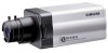
12. Operating Instructions Lens Fixing In case of CS lenses E Turn the CS lens clockwise until it is fixed as shown as follows. CS lens Setting Lens Selection Switch When lens mounting is completed, set the Lens selection Switch on the side of the camera according to the mounted lens type. - Samsung SCC-B2300 | Service Manual - Page 71
Instructions 3 Third, connect the power cable. ① AC24V/DC12V Power Input Camera. Connect 2 lines of the power adapter using a phillips screwdriver to the E power IN Terminal of the camera back focus of the camera. Rear View AC24V/DC12V Camera (SCC-B2391(P)/B2300) E 1. L/L Samsung Electronics - Samsung SCC-B2300 | Service Manual - Page 72
Camera (SCC-B1391(P)) E ⑤ ➁ ➂ ➃ ➅ ⑦ ① AC230V Camera (SCC-1091P) ⑤ ① ➁ ➂ ➃ ➅ ⑦ Operating Instructions ① Power connection port AC24V/DC12V Camera : It is a port connected to the power adaptor cable. AC230V Camera switch with the Manual Iris Lens. While natrium lamp Samsung Electronics ➅ - Samsung SCC-B2300 | Service Manual - Page 73
Operating Instructions MEMO 12-4 Samsung Electronics - Samsung SCC-B2300 | Service Manual - Page 74
signals are filtered. • B/W Image(Night Mode) : high frequency signal is filtered. * To activate the CCD, voltage should be input to V1~V4, VSUB, RG, H1~2. Samsung Electronics - Samsung SCC-B2300 | Service Manual - Page 75
LE EL A CC T A CCLP S S S CS CLP MS MS CS CLP PE SA E C T AC E C S IT S CAM S SET AC CLP T T LK S T ig. PS T cc .C. T SET P LK S CLP Samsung Electronics - Samsung SCC-B2300 | Service Manual - Page 76
CONVERTING of DRVOUT signal. • Blemish Compensation. • Digital Camera Processing. • Video Signal Encoding. • White Balance(u-COM is . 2. DRVOUT(IC101-3) from CCD BD is A/D Converted and handled by Digital Camera Processing, then it goes to Encoding block. 3. Encoding block does digital encoding and - Samsung SCC-B2300 | Service Manual - Page 77
Matching(75Ω), and output to BNC CONNECTOR of READ BD. Supplying VOUT to IC113-6 through C154 is for eliminating the SAG signal of VIDEO(VOUT). Samsung Electronics - Samsung SCC-B2300 | Service Manual - Page 78
13-2 Internal/LineLock Signal System Diagram 13-2-1 Block Diagram Circuit perating escription ig. Internal/LineLoc Signal System iagram Samsung Electronics - Samsung SCC-B2300 | Service Manual - Page 79
and X101. • SCC-B2391 / SCC-B1391 : 28.636363MHz • SCC-B2391P / SCC-B1391P / SCC-B2091P / SCC-B1091P : 28.37500MHz • SCC-2300 : 38.13986MHz 4) should be 2.5Volts by adjusting variable condenser C130. (See the Adjustment guide) 7) VCO which is composed by D102, C127, R138, L104, Samsung Electronics - Samsung SCC-B2300 | Service Manual - Page 80
13-3 Iris Signal System Diagram 13-3-1 Block Diagram Circuit perating escription ig. Iris Signal System iagram 13-3-2 S 501 o AI BD selects the lens type( DC LENS or VIDEO LENS ) • SW501 OFF : DC LENS • SW501 ON : VIDEO LENS Samsung Electronics - Samsung SCC-B2300 | Service Manual - Page 81
ELC A EA ALC A EA I CASE ELC I CASE ALC CC TP T SI AL Transfered to I E SI AL ig. elation between ELC/ALC/A C when shooting the A SCALE C A T Samsung Electronics - Samsung SCC-B2300 | Service Manual - Page 82
filter. A T Mode 1) Locate the SW401 of REAR BD at the "AUTO" position. 2) u-COM controls DAYNIGHT automatically. In the bright area, camera works in COLOR Mode, in the dark area, camera works in B/W Mode. E T Mode 1) Locate the SW401 of REAR BD at the "EXT" position. 2) If input signal of CN403 is - Samsung SCC-B2300 | Service Manual - Page 83
Circuit perating escription 13-5 Power System Diagram 13-5-1 Block Diagram(AC2 V/DC12V) Rectifier ig. Power System iagram AC / C 13-5-2 Block Diagram(AC230V) Rectifier (D1~D4) ig. Power System iagram AC Samsung Electronics - Samsung SCC-B2300 | Service Manual - Page 84
power is input. • BD01~05, C1, C2, LF1, BD5, : for the safety requirement • F1 : FUSE(Formal Spec : 125V 2.0A) 3) SWITCHING module switches the signal using RCC(RINGING CHOKE CONVERTOR : an isolated oscillation POWER) method at R228 makes -6.8V. +15V and 6.8V is used for CCD. Samsung Electronics - Samsung SCC-B2300 | Service Manual - Page 85
Circuit perating escription MEMO Samsung Electronics - Samsung SCC-B2300 | Service Manual - Page 86
DayNight Camera (SCC-B2391/B2391P/B2091P) Ů High-Resolution Camera (SCC-B1391/B1391P/B1091P) Ů Economy DayNight Camera (SCC-B2300) Ů High Resolution Color Camera : 540 TV Lines. This camera shows 2) Gain-Up processing more than 30dB. Amplication Circuit High resolution Samsung Electronics 14-1 - Samsung SCC-B2300 | Service Manual - Page 87
Table SCC TSC . Mega Pi els AC z/ C SCC P SCC PAL . Mega Pi els / Color/ . / . Color/ A T /E T AC z/ C AC P SCC TSC . Mega Pi els / Color/ . / . Color/ z AC z/ C SCC TSC . Mega Pi els SCC P PAL . Mega Pi els SCC P . one AC z/ C AC z/ C AC z Samsung Electronics
-
 1
1 -
 2
2 -
 3
3 -
 4
4 -
 5
5 -
 6
6 -
 7
7 -
8
-
9
-
10
-
11
-
12
-
13
-
14
-
15
-
16
-
17
-
18
-
19
-
20
-
21
-
22
-
23
-
24
-
25
-
26
-
27
-
28
-
29
-
30
-
31
-
32
-
33
-
34
-
35
-
36
-
37
-
38
-
39
-
40
-
41
-
42
-
43
-
44
-
45
-
46
-
47
-
48
-
49
-
50
-
51
-
52
-
53
-
54
-
55
-
56
-
57
-
58
-
59
-
60
-
61
-
62
-
63
-
64
-
65
-
66
-
67
-
68
-
69
-
70
-
71
-
72
-
73
-
74
-
75
-
76
-
77
-
78
-
79
-
80
-
81
-
82
-
83
-
84
-
85
-
86
-
87
 |
 |

DIGITAL COLOR CAMERA
SCC-B2391(P)/SCC-B2091P
SCC-B1391(P)/SCC-B1091P
SCC-B2300
SERVICE
Œ
1/3” Super-HAD IT CCD
´
Hi-resolution DSP (Digital Signal Processing)
ˇ
Superior Back Light Adjustment Function
¨
Digital Power Supply Synchronization Method
ˆ
DAY/NIGHT CAMERA
(SCC-B2391(P)/SCC-B2091P/SCC-B2300)
Manual
DIGITAL COLOR CAMERA
Merit & Character regarding Product
SERVICE MANUAL
SCC-B2391(P)/SCC-B2091P/SCC-1391(P)/SCC-B1091P/SCC-B2300
ELECTRONICS
© Samsung Electronics Co., Ltd.
JUL. 2005
Printed in Korea
MF82-00192A
This Service Manual is a property of Samsung Electronics Co .,Ltd.
Any unauthorized use of Manual can be punished under applicable
International and/or domestic law.