Samsung SRP-350PG User Manual - Page 8
Rev. 1.02 - printers
 |
View all Samsung SRP-350PG manuals
Add to My Manuals
Save this manual to your list of manuals |
Page 8 highlights
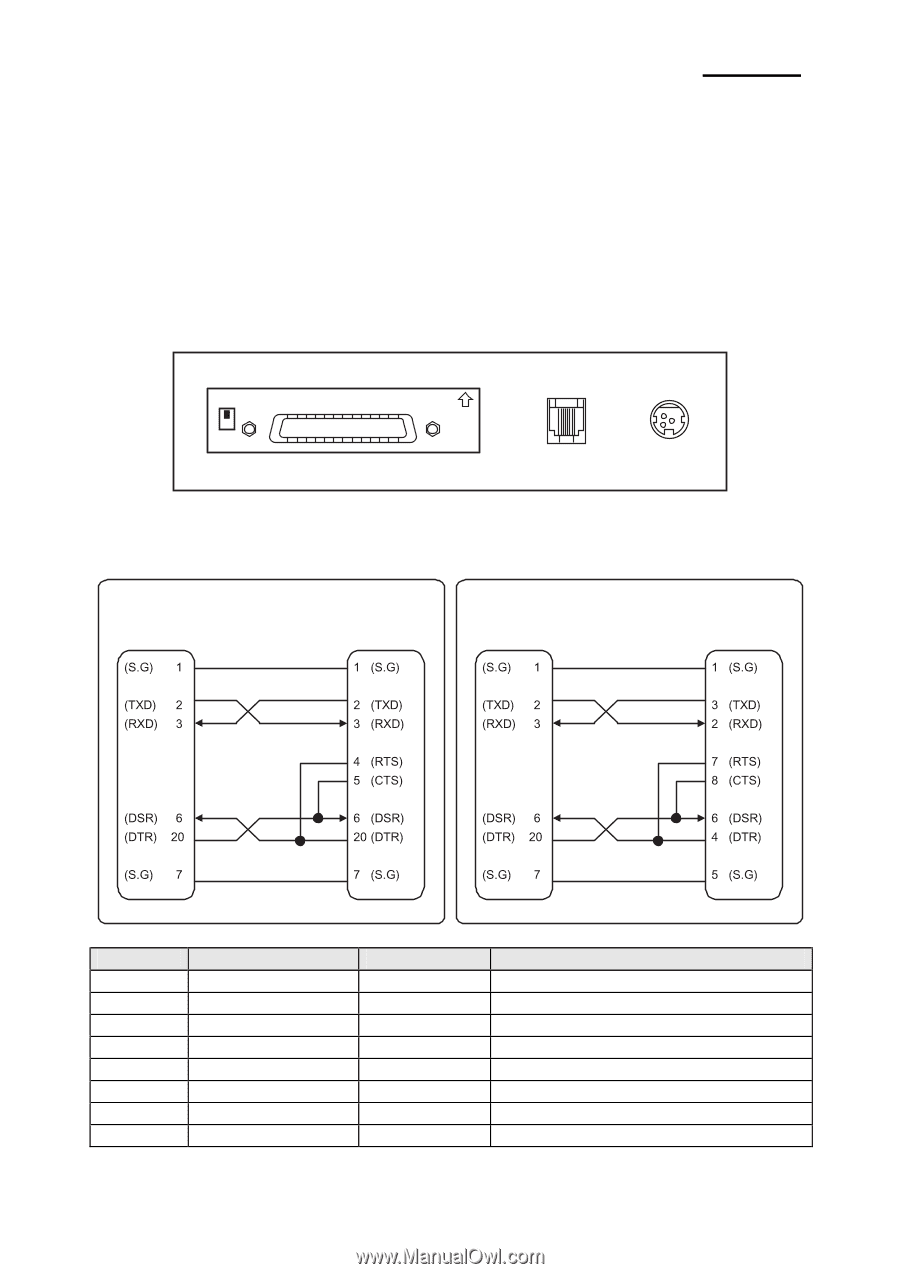
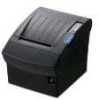
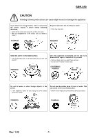
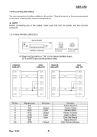
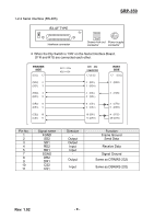
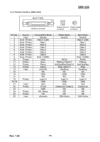
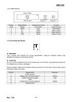
SRP-350 1-2 Connecting the Cables You can connect up the three cables to the printer. They all connect to the connector panel on the back of the printer, which is shown below: ※ NOTE Before connecting any of the cables, make sure that both the printer and the host are turned off. 1-2-1 Serial Interface (RS-232C) IFA-S TYPE ON Interface connector Drawer kick-out Power supply connector connector ※ When the Dip Switch is "ON" on the Serial Interface Board, DTR and RTS are connected each other. PRINTER SIDE (25P) HOST SIDE (25P) PRINTER SIDE (25P) HOST SIDE (9P) Pin No. 1 2 3 4 5 6 7 20 Signal name FG TxD RxD RTS CTS DSR SG DTR Direction - Output Input Output Input Input Output Rev. 1.02 - 8 - Function Frame Ground Transmit Data Receive Data Ready To Send Clear To Send Data Set Ready Signal Ground Data Terminal Ready
-
 1
1 -
2
-
 3
3 -
 4
4 -
 5
5 -
 6
6 -
 7
7 -
 8
8 -
 9
9 -
 10
10 -
 11
11 -
 12
12 -
 13
13 -
14
-
15
-
16
-
17
-
18
-
19
-
20
-
21
 |
 |