Samsung TXJ1366 Service Manual
Samsung TXJ1366 Manual
 |
View all Samsung TXJ1366 manuals
Add to My Manuals
Save this manual to your list of manuals |
Samsung TXJ1366 manual content summary:
- Samsung TXJ1366 | Service Manual - Page 1
COLOR TELEVISION RECEIVER Chassis : Model: K15A TXJ1366 TXJ1367 TXJ1396 TXJ1966 TXJ1996 COLOR TELEVISION RECEIVER CONTENTS 1. Precautions 2. Specifications 3. Disassembly and Reassembly 4. Alignment and Adjustments 5. Troubleshooting 6. Exploded Views and Parts List 7. Electric Parts List 8. - Samsung TXJ1366 | Service Manual - Page 2
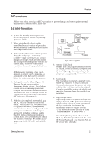
they are serviced. (X-ray protection circuits also may be called Òhorizontal disableÓ or Òhold-downÓ.) Heed the high voltage limits. These include the XÐray Protection Specifications Label, and the Product Safety and X-ray Warning Note on the service data schematic. Samsung Electronics 1-1 - Samsung TXJ1366 | Service Manual - Page 3
AC plug polarity. These units can be safely serviced only if an isolation transformer inserted between the receiver and the power source. 13. Some TV chassis have a secondary ground system in addition to characteristics as the original might create shock, fire or other hazards. Samsung Electronics - Samsung TXJ1366 | Service Manual - Page 4
read the "Safety Precautions" section of this manual. If some unforeseen circumstance creates a conflict between the servicing and safety precautions, always follow the safety ground before connecting the positive lead; always remove the instrumentÕs ground lead last. Samsung Electronics 1-3 - Samsung TXJ1366 | Service Manual - Page 5
handling unpackaged replacement ESDs. Motions such as brushing clothes together, or lifting a foot from a carpeted floor can generate enough static electricity to damage an ESD. 1-4 Samsung Electronics - Samsung TXJ1366 | Service Manual - Page 6
ELECTRONICS © Samsung Electronics Co., Ltd. SEP. 1999 Printed in Korea 3K15A-1425 - Samsung TXJ1366 | Service Manual - Page 7
Specifications Television System Power Consumption Picture Tube Power Requirement Operating System Tuning Ranges Antenna Input Impedance Intermediate Frequency Speaker Impedance 14"/20"/21" NTSC COLOR TV SIGNAL Dual : 8 ohm 3W x 2 Dual : 16 ohm , 3W x 2 (CT-33H1, CT-50H1) Samsung Electronics 2-1 - Samsung TXJ1366 | Service Manual - Page 8
3. Disassembly and Reassembly 3-1 Back Cover Removeal Disassembly and Reassembly Fig. 3-1 1. After removing the screws, pull the cabinet backwards. Samsung Electronics 3-1 - Samsung TXJ1366 | Service Manual - Page 9
FBT is charged with high voltage. Before removing the Anode Cap, discharge the voltage through one of the heat sinks on the main board. Fig. 3-3 3-2 Samsung Electronics - Samsung TXJ1366 | Service Manual - Page 10
3-3 Speaker Removal 1. Loosen the screws and remove the speakers. Disassembly and Reassembly Fig. 3-4 Samsung Electronics 3-3 - Samsung TXJ1366 | Service Manual - Page 11
and Reassembly 3-4 CRT Removel Fig. 3-5 1. Spread a soft mat on the floor. Place the TV set face down. 2. Remove the 4 nuts mounting the CRT to the front cabinet. 3. Lift the picture tube or apply excessive pressure. Fractures of the glass may cause an implosion. 3-4 Samsung Electronics - Samsung TXJ1366 | Service Manual - Page 12
XX SCR XX VS XX STT XXX HS XX GG XXX SS XX BG XXX SVC : MUTE Samsung Electronics Alignment and Adjustments Change the data with "Volume +, - " keys. VCO 71 Return to the Service mode by pressing MENU. AGC XX RC XXX VCO XX GC XXX SBT XX BC XX SCT XX - Samsung TXJ1366 | Service Manual - Page 13
Press volume + key. POWER OFF 4-1-4 Service Mode Adjustments ADJUSTMENT PATTERN OPTION RESET 1. for other adjustments. 3. Set OPTION data. 4-1-5 Service Mode Adjustment Ratings No Item Function 1 AGC RF 0~31 15 0~31 4 Note : The initial MICOM data values take effect when IC902 is replaced - Samsung TXJ1366 | Service Manual - Page 14
Instructions 1. Usually, a color TV be the final step in servicing. 2. Turn the power will disappear. 4. The TV must remain in this off the TV and allow enter the Service Mode, refer to Fig. 4-1 (Service Mode Adjustment pin for R237. 3. Adjust VCO in the service mode to set IC101 Pin 44 (AFT) to - Samsung TXJ1366 | Service Manual - Page 15
R-OUT with an oscilloscope. 4. Set RC, BC, GC data to 0 in the Service Mode. 5. Adjust SCT to 2.40 ± 0.1Vp-p 2.5V_+ 0.1Vpp 4-2-10 Sub- rainbow pattern. 2. Check CN201 B-OUT with an oscilloscope. 3. Adjust STT in the service mode until the 6th peak is the highest and the 5th and 7th peaks have equal - Samsung TXJ1366 | Service Manual - Page 16
for 30 minutes. 3. Check the data in the service mode: RC, GC, BC are 0 and SB Adjust GG,BG in the Service Mode. 3. Recheck in low center adjustment, enter into the service mode. 3. Adjust VA so . 2. Enter into the service mode. 3. Adjust HS to minutes. 3. Enter the Service Mode and set SB to the point - Samsung TXJ1366 | Service Manual - Page 17
MEMO 4-6 Samsung Electronics - Samsung TXJ1366 | Service Manual - Page 18
5-1 No Power Troubleshooting No Power OFF Abnormal Check Fuse. Check LED when AC code is plugged. Normal ON Check IC802. Abnormal Check/Replace IC802, R812, D856. Check Normal (0.5 ~ 3V) Pin 4 Voltage Check/Replace PC802, DZ807 Check/Replace DZ802, DZ803, D806 Samsung Electronics 5-1 - Samsung TXJ1366 | Service Manual - Page 19
Troubleshooting 5-2 No Sound Normal Abnormal Check Waveform of IC601 Pin 1. Normal Check Waveform of IC201 Abnormal Pin 52. Check Waveform of Voltage of IC601 and IC602 Normal (approx. 12V) Pin 5. Abnormal Check Power 12V Line Voltage. Replace IC601 and IC602. 5-2 Samsung Electronics - Samsung TXJ1366 | Service Manual - Page 20
5-3 Horizontal Line Appears Troubleshooting Single Horizontal Line Normal (24V) Check 24V-C Voltage. Abnormal Abnormal Check Waveform of IC201 Pins 22,24. Check Whether a horizontal line appears in O.K Normal the service mode.. NG Check/Replace Check/Replace IC201. IC301. Check FBT - Samsung TXJ1366 | Service Manual - Page 21
Troubleshooting 5-4 No Signal No Signal Abnormal Check each tuner terminal voltage. 7,8 waveform. Normal Abnormal Replace tuner. Check whether AGC and AFTadjustment are normal in the service mode. Normal Abnormal Check IC201 Pin 47 waveform level. Abnormal Readjust AGC and AFT. Normal - Samsung TXJ1366 | Service Manual - Page 22
6. Exploded Views & Parts List 6-1 TXJ1366, TXJ1367, TXJ1396 Exploded Views & Parts List No Code No 1 AA92-30161EA AA64-00162A 1-1 AA64- 3-1 6002-000514 3-2 L7000-0132 AA42-00001A 4 AA39-10007Y Samsung Electronics Description ASSY-CABINET,FRONT CABINET-FRONT BADGE-BRAND KNOB-POWER - Samsung TXJ1366 | Service Manual - Page 23
Exploded Views & Parts List 6-2 TXJ1966, TXJ1996 No Code No 1 AA92-30161NA AA64-00152A 1-1 AA64-70127F 1-2 AA64-00156B 1-3 AA61-60003J 1-4 AA61- 1 1 1 WIN+CF 1 1 1 2 SPK+CF 1 4 4 1 4 CB+CF 1 TXJ1996 1 TXJ1966 -,EP2/YES,SPT-2 18AWGx2C,2.4m 1 CORD/P Samsung Electronics - Samsung TXJ1366 | Service Manual - Page 24
7. Electric Parts List Electric Parts List 7-1 Part Differences (by screen size 7-1 7-2 TXJ1366 (TXJ1996 and TXJ1366 Dissimilar Parts 7-9 7-3 TXJ1996 ...7-9 Samsung Electronics 7-1 - Samsung TXJ1366 | Service Manual - Page 25
Samsung Electronics 7-2 7-1 Part Differences (by screen size) INC No. Loc. No. H SPECIFICATION " 1P 20" 1P ASSY- 14" A34KQV42X,+380mG,14",BARE 8 CRT 20" A48KRD82X(H),+380MG,20",BARE CODE No. AA03-10001D AA03-10029W AA27-50001K AA27-50004W AA27-60001E AA27-60001D 3704-001089 3704-001090 AA26- - Samsung TXJ1366 | Service Manual - Page 26
7-3 Samsung Electronics 7-1-1 Inch Option INC No. Loc. No. H 14" 1 C402 20" 14" 2 C403 20" 471 50V C-C 471 50V C-E 1uF 50V HR C-E 1uF 50V HR C-P 473 100V C-P 683-J 50V U.S.A CODE No. 2306-000253 2306-000355 2201-000467 2201-000406 2306-000004 2306-000193 AA27-30001B AA27-30001B 2001-000020 2001- - Samsung TXJ1366 | Service Manual - Page 27
Samsung Electronics 7-4 INC No. Loc. No. H 14" 13 C311 20" 14" 8T R-C 30K-J 1/8T R-M 62K-J 1/8T R-M.O 330-J 1W R-M.O 510-J 1W R-F 2W 1.0 " R-F 2W 1.5 " X X U.S.A CODE No. 2401-001333 2401-001333 2001-000864 2004-001990 2003-001036 2003-000436 AA39-20109D AA39-20109A 2 0 01-000660 2 0 04-001213 - Samsung TXJ1366 | Service Manual - Page 28
7-5 Samsung Electronics INC No. Loc. No. H 14" 25 C216 20" 14" 26 COMP 4.7K1/2T R-COMP 4.7K1/2T X R-COMP 4.7K1/2T X FSV-14A001,14",125V FSV-20A001,14",125V U.S.A CODE No. 2201-000354 2201-000354 2004-000995 2001-000221 2004-000995 2001-000221 2004-000995 2001-000221 2001-000290 2001-000331 2001 - Samsung TXJ1366 | Service Manual - Page 29
Samsung Electronics 7-6 7-1-2 AC Input Option No. Loc. No. SPECIFICATION AC 110V ONLY 1 C801 4 02-000132 FREE VOLT SPECIFICATION C-E:220uF 400V C-C 400V 332 X STR S0680 R-M,OXIDE 2W33K R-M,OXIDE 2W33K EER 354311 CODE No. 2 4 01-002298 2 2 01-000446 X AA9 6-50298D 2 0 03-000994 2 0 03-000994 - Samsung TXJ1366 | Service Manual - Page 30
7-7 Samsung Electronics 7-1-4 X-Ray Option No. Loc. No. 1 CX01 2 CX02 3 CX03 4 KSA539-Y R-C 180K 1/8T R-C 18K 1/8T R-M 4.3K-F 1/2T R-M 11K-F 1/2T R-C 22K 1/8T JUMPER R-C 51K 1/8T X X-RAY USED CODE No. 2 2 02-000127 2 4 01-000480 2 4 01-000480 2 2 01-000556 0 4 03-000297 0 4 02-000132 3 8 - Samsung TXJ1366 | Service Manual - Page 31
/ 1 AMP) No. Loc. No. SPECIFICATION CODE No. 1 IC602 X X 2 C652 X ~1H SYSTEM (2 SPKs / 1 AMP) SPECIFICATION CODE No. X X X X X X X X 2 SPKs / 2 AMPs) SPECIFICATION CODE No. ASSY-H/S LA4425 AA9 6-50392A EARPHONE A/V POST HEADER 7P JUMPER JUMPER CODE No. AA9 5-90030M 3 7 11 - Samsung TXJ1366 | Service Manual - Page 32
Code No. Description ; Specification Remark Loc. No. Code No. Description ; Specification Remark TXJ1366X/XAA, TXJ1366X/XAC, TXJ1367/XAC TXJ1396X/XAA, TXJ1396X/XAC ASSY-PCB,MAIN * AA94-10133F2 ASSY-PCB,MAIN(COM);K15A(0),S/V,13,BLK, TXJ1366 -DEGAUSSING;20POLYVINI Samsung Electronics 7-9 - Samsung TXJ1366 | Service Manual - Page 33
Electric Parts List 7-17 TXJ1996 Loc. No. Code No. Description ; Specification Remark Loc. No. Code No. Description ; Specification Remark TXJ1966X/XAA, TXJ1966X/XAC, TXJ1996X/XAA ASSY-PCB,MAIN ,3.32D202 0401-000005 DIODE;1N4148TAPG D203 0401-000005 DIODE;1N4148TAPG 7-10 Samsung Electronics - Samsung TXJ1366 | Service Manual - Page 34
No. Code No. Description ; Specification Remark Loc. No. Code No ;24C020,256X8BIT,DIP,8P,300MIL JA601 3722-000143 JACK-PHONE;1P,3.4MM,-,MBAG JA701 3722-000162 JACK-PIN;2P,3.4MM INDUCTOR-AXIAL;10UH,10%,2.8X7M ASSY-LED,GUIDE;AA61-50055A,DL-G7GA,GREEN THERMISTOR;KL11L4R7-3. Samsung Electronics 7-11 - Samsung TXJ1366 | Service Manual - Page 35
Electric Parts List Loc. No. Code No. Description ; Specification Remark Loc. No. Code No. Description ; Specification Remark R237 R239 R240 R241 R242 R251 R252 R253 R257 R301 R302 R303 15V,20MA,90-170GF, SWITCH-TACT;15V,20MA,90-170GF, SWITCH-TACT;15V,20MA,90-170GF, 7-12 Samsung Electronics - Samsung TXJ1366 | Service Manual - Page 36
Electric Parts List Loc. No. Code No. Description ; Specification Remark Loc. No. Code No. Description ; Specification Remark SW904 SW905 SW906 ! T401 ! T444 ! T801 ! TU01 ! V999 X201 M4,L12,ZP SPRING-CS;-,-,SUS304,0.5,OD6,H WINDOW-REMOCON;-,20F2,-,PC,VO,VIOLET,- Samsung Electronics 7-13 - Samsung TXJ1366 | Service Manual - Page 37
MEMO 7-14 Samsung Electronics - Samsung TXJ1366 | Service Manual - Page 38
.5V PC802 PHOTO COULPER VERTICAL-AMP KA2131 (125V) T444* F.B.T 14" : FSV14A001 20" : FSV20A001 21" : FSV20A001 (12.5V) IC802 (5V) MICOM MULTI-REGULATOR KA7631 1CHIP (9V) Samsung Electronics 8-1 - Samsung TXJ1366 | Service Manual - Page 39
9. PCB Layout 9-1 PCB-MAIN Samsung Electronics PCB Layout Loc. No. X Y DIODE D101 53 150 D102 56 130 D103 71 141 D201 135 196 D202 96 105 D203 96 107 D204 - Samsung TXJ1366 | Service Manual - Page 40
10. Wiring Diagram Wiring Diagram SPEAKER CRT H1 H2 V1 V2 S G CN601 S G B G R 9V GND 180V GND HT CN201 MAIN ASSY CCRRT PPCCBB B G R 9V GND 180V GND HT CCNN550011 CN401 H1 H2 V1 V2 V1 R+ R- V0 GND AI A0 CN701 A/V ASSY V1 R+ RV0 GND AI A0 CN702 Samsung Electronics 10-1 - Samsung TXJ1366 | Service Manual - Page 41
11. Schematic Diagrams 11-1 MAIN 1/4 Samsung Electronics Schematic Diagrams : Power Line : Signal Line 11-1 - Samsung TXJ1366 | Service Manual - Page 42
Schematic Diagrams 11-2 MAIN 2/4 11-2 TP13 IC201 30PIN TP14 IC201 32PIN TP18 TP21 TP20 TP19 TP17 TP16 TP15 TP14 TP13 TP2 TP1 TP3 TP5 TP6 TP2 IC201 4 PIN TP3 IC201 7PIN TP4 IC201 19PIN TP5 IC201 20PIN TP6 IC201 21PIN TP7 IC201 22PIN TP8 IC201 23PIN TP9 IC201 24PIN Samsung Electronics - Samsung TXJ1366 | Service Manual - Page 43
11-3 MAIN 3/4 TP25 Samsung Electronics TP24 TP27 TP26 Schematic Diagrams TP24 TP25 IC801 1 PIN TP26 TP27 T444 10 PIN : Power Line Si l Li 11-3 - Samsung TXJ1366 | Service Manual - Page 44
Schematic Diagrams 11-4 MAIN 4/4 11-4 : Power Line : Signal Line Samsung Electronics
-
 1
1 -
 2
2 -
 3
3 -
 4
4 -
 5
5 -
 6
6 -
 7
7 -
8
-
9
-
10
-
11
-
12
-
13
-
14
-
15
-
16
-
17
-
18
-
19
-
20
-
21
-
22
-
23
-
24
-
25
-
26
-
27
-
28
-
29
-
30
-
31
-
32
-
33
-
34
-
35
-
36
-
37
-
38
-
39
-
40
-
41
-
42
-
43
-
44
 |
 |

COLOR TELEVISION RECEIVER
Chassis :
K15A
Model:
TXJ1366
TXJ1367
TXJ1396
TXJ1966
TXJ1996
COLOR TELEVISION RECEIVER
CONTENTS
Precautions
Specifications
Disassembly and Reassembly
Alignment and Adjustments
Troubleshooting
Exploded Views and Parts List
Electric Parts List
Block Diagram
PCB Layout
Wiring Diagrams
Schematic Diagrams
1.
2.
3.
4.
5.
6.
7.
8.
9.
10.
11.