Sanyo DP42740 Owners Manual - Page 6
Hdtv Input/output Reference
 |
UPC - 086483078262
View all Sanyo DP42740 manuals
Add to My Manuals
Save this manual to your list of manuals |
Page 6 highlights
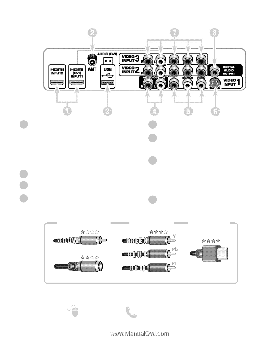
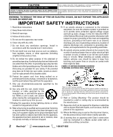
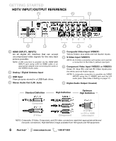
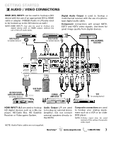
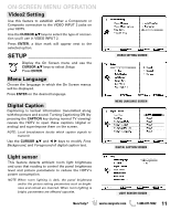
GETTING STARTED HDTV INPUT/OUTPUT REFERENCE 1 HDMI (INPUT1, INPUT2) An all digital AV interface that can accept uncompressed video signals for the very best picture possible. NOTE: A DVI conection is possible via the HDMI (DVI) INPUT1 jack using a DVI to HDMI cable or an appropriate adapter and connecting the audio to the VIDEO3 Audio jacks. 2 Analog / Digital Antenna Input 3 USB Input View pictures stored in a USB flash drive. 4 Stereo Audio Out (L/R) Jacks 5 Composite Video Input (VIDEO1) Yellow (Video), plus white and red (Audio) inputs. 6 S-Video Input (VIDEO1) NOTE: An S-Video connection will replace and override a connection to the Video1 (yellow) input jack. 7 Component Video Input (VIDEO2 or VIDEO3) Green (Y), blue (Pb), and red (Pr) Video inputs plus the white and red Audio inputs. NOTE: A composite connection is possible via VIDEO INPUT2 using the Y (VIDEO) jack and the L/R audio jacks. (See Video 2 Setting on page 11.) 8 Digital Audio Output (Coaxial) Standard Definition High Definition Optimum High Definition Composite S-Video Component H D M I (or DVI to HDMI cable/adapter) NOTE: Composite, S-Video, Component, and DVI video connections need their appropriate white and red audio connections. High Definition image available from HD signals and HD equipment. 6 Need help? www.sanyoctv.com 1-800-877-5032
-
 1
1 -
 2
2 -
 3
3 -
 4
4 -
 5
5 -
 6
6 -
 7
7 -
 8
8 -
 9
9 -
 10
10 -
 11
11 -
 12
12 -
13
-
14
-
15
-
16
-
17
-
18
-
19
-
20
-
21
-
22
-
23
-
24
-
25
-
26
-
27
-
28
-
29
-
30
-
31
-
32
-
33
-
34
-
35
-
36
-
37
-
38
-
39
-
40
-
41
-
42
-
43
-
44
-
45
-
46
-
47
-
48
 |
 |