Sanyo PDG-DHT8000L Owners Manual - Page 21
Connecting to Video Equipment
 |
View all Sanyo PDG-DHT8000L manuals
Add to My Manuals
Save this manual to your list of manuals |
Page 21 highlights
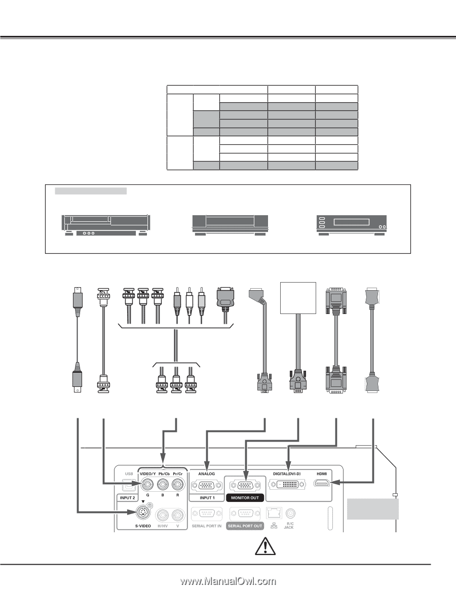
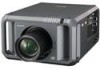
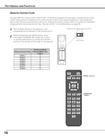
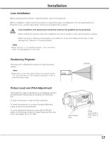
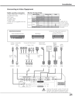
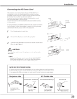
Installation Connecting to Video Equipment Cables used for connection • Video Cable (BNC x 3, BNC x 1) • SCART-VGA Cable • DVI Cable • S-Video Cable • HDMI Cable ( Cables are not supplied with the projector.) Monitor Out Signal Table Input Terminal RGB (PC analog) D-sub15 RGB (SCART) Input 1 DVI-D RGB (PC digital) RGB (AV HDCP) HDMI HDMI RGB Input 2 5BNC Video Y-Pb/Cb-Pr/Cr S-video S-video Monitor Out YES NO NO NO NO YES YES YES NO Cable Q A cable with one end D-sub 15 and Q the other end (Black box) compatible with Q each equipment is necessary. Video Source (example) Video Cassette Recorder DVD Player Component video output equipment. (such as DVD player or high-definition TV source.) S-Video Composite Output Video Output Component Video Output Y Pb/Cb Pr/Cr RGB SCART 21-pin Output Refer to the Monitor Out Signal Table (above). Digital Output (HDCP HDMI compatible) Output S-Video BNC Cable Cable BNC Cable SCART-VGA Cable DVI Cable HDMI Cable S-VIDEO VIDEO Y-Pb/Cb-Pr/Cr ANALOG MONITOR DIGITAL OUT HDMI Terminals of the projector Unplug the power cords of both the projector and external equipment from the AC outlet before connecting cables. 21
-
 1
1 -
2
-
3
-
4
-
5
-
6
-
7
-
8
-
9
-
10
-
11
-
12
-
13
-
14
-
15
-
 16
16 -
 17
17 -
 18
18 -
 19
19 -
 20
20 -
 21
21 -
 22
22 -
 23
23 -
 24
24 -
 25
25 -
 26
26 -
27
-
28
-
29
-
30
-
31
-
32
-
33
-
34
-
35
-
36
-
37
-
38
-
39
-
40
-
41
-
42
-
43
-
44
-
45
-
46
-
47
-
48
-
49
-
50
-
51
-
52
-
53
-
54
-
55
-
56
-
57
-
58
-
59
-
60
-
61
-
62
-
63
-
64
-
65
-
66
-
67
-
68
-
69
-
70
-
71
-
72
-
73
-
74
-
75
-
76
-
77
-
78
-
79
-
80
-
81
-
82
-
83
-
84
-
85
-
86
-
87
-
88
-
89
-
90
-
91
-
92
-
93
-
94
 |
 |