Sanyo PLC XT35L Owners Manual
Sanyo PLC XT35L - XGA LCD Projector Manual
 |
UPC - 086483069215
View all Sanyo PLC XT35L manuals
Add to My Manuals
Save this manual to your list of manuals |
Sanyo PLC XT35L manual content summary:
- Sanyo PLC XT35L | Owners Manual - Page 1
Multimedia Projector MODEL PLC-XT35/PLC-XT35L* (*Models without lens.) Owner's Manual - Sanyo PLC XT35L | Owners Manual - Page 2
Multiple Interface Terminals The projector has several interface terminals that can support various types of equipment and signals (pp.11-12). ◆ Lamp Control Brightness of the projection lamp can be selected (p.49). ✔Notes: • The On-Screen Menu and figures in this manual may differ slightly from - Sanyo PLC XT35L | Owners Manual - Page 3
49 Maintenance and Filter Cleaning 58 Cleaning the Filter 58 Resetting the Filter Counter 58 Lamp Replacement 59 Resetting the Lamp Counter 60 Warning Indicators 61 Cleaning the Projection Lens 62 Cleaning the Projector Cabinet 62 Appendix 63 Troubleshooting 63 Menu Tree - Sanyo PLC XT35L | Owners Manual - Page 4
operate improperly, read this manual again, check operations and cable connections and try the solutions in the "Troubleshooting" section in the back of this booklet. If the problem still persists, contact the dealer where you purchased the projector or the service center. CAUTION RISK OF ELECTRIC - Sanyo PLC XT35L | Owners Manual - Page 5
or sold with the projector. Wall or shelf mounting should follow the manufacturer's instructions, and should use a mounting kit approved by the . Refer all servicing to qualified service personnel. Unplug this projector from wall outlet and refer servicing to qualified service personnel under the - Sanyo PLC XT35L | Owners Manual - Page 6
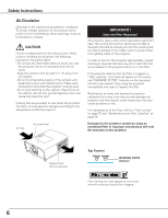
Safety Instructions Air Circulation Openings in the cabinet are provided for ventilation. is changed according to the temperature inside the projector. Air flow Air Intake Vent IMPORTANT! Clean the Filter Regularly!! The projector uses a lamp which generates significant heat. The cooling fans and - Sanyo PLC XT35L | Owners Manual - Page 7
Safety Instructions Installing the Projector in Proper Directions Use the projector properly in specified positions. Improper positioning may reduce the lamp life and result in severe accident or fire hazard. This projector can project the picture in upward, downward, or inclined position in - Sanyo PLC XT35L | Owners Manual - Page 8
courier or any other transport service, consult your dealer. - Do not put the projector in a case before it is cooled enough. Cautions in Handling the Projector Do not hold the lens when lifting or moving the projector. Doing so may cause damage to the lens and the projector. Care must be taken when - Sanyo PLC XT35L | Owners Manual - Page 9
the equipment unless otherwise specified in the instructions. If such changes or modifications should be made, you could be required to stop operation of the equipment. Model Number(s) Trade Name Responsible party Address : PLC-XT35, PLC-XT35L : Sanyo : SANYO FISHER COMPANY : 21605 Plummer Street - Sanyo PLC XT35L | Owners Manual - Page 10
rt e yu i o Back !1 !2 !0 ✽ !3 !4 !5 !6 Bottom !7 o q Filter w Speaker e Lens Release Button r Top Controls and Indicators t Maintenance Cover WARNING: For maintenance use only. Do not open. y Lens Cap (for PLC-XT35) CAUTION Do not turn on the projector with the lens cap attached. High - Sanyo PLC XT35L | Owners Manual - Page 11
from video equipment to this jack (p.21). t USB CONNECTOR (Series B) Use this connector when controlling a computer with the remote control of the projector. Connect the USB terminal of your computer to this connector with the supplied USB cable (p.20). o AUDIO 1 JACK Connect the audio output - Sanyo PLC XT35L | Owners Manual - Page 12
) This terminal outputs the video signal from computer to external video equipment (pp.20, 22). !3 CONTROL PORT CONNECTOR When controlling the projector from a computer, connect the computer to this connector with a control cable. !4 Infrared Remote Receiver (Back) The infrared remote receiver is - Sanyo PLC XT35L | Owners Manual - Page 13
indicator Lights yellow when the projection lamp reaches its end of life (pp.59, 69). e ON/STAND-BY button Turn the projector on or off (pp.24-25). r INPUT button Select an input source (pp.34-35). t LENS button Enter the focus, zoom, and lens shift adjustment mode (p.30). y POINT ed7 8 (VOLUME - Sanyo PLC XT35L | Owners Manual - Page 14
32). r Laser Light window A laser beam is emitted from here (p.32). t ON button Turn the projector on (p.24). !0 Presentation Pointer button Move a pointer of the projector or a pointer for wireless mouse operation (pp.32-33). !1 INFO. button Display the input source information (p.28). !2 L-Click - Sanyo PLC XT35L | Owners Manual - Page 15
30). @1 NO SHOW button Temporarily turn off the image on the screen (p.31). @2 KEYSTONE button Correct keystone distortion (p.31). @3 LENS SHIFT button Select the Lens Shift function (p.30). @4 SCREEN button Select the screen size (p.30). @5 R-CLICK button Acts as the right mouse button for wireless - Sanyo PLC XT35L | Owners Manual - Page 16
battery is replaced by an incorrect type. ● Dispose of used batteries according to the instructions. Remote Control Receivers and Operating Range 16.4' Point the remote control toward the projector (to Infrared (5 m) Remote Receivers) when pressing the buttons. Maximum operating range for the - Sanyo PLC XT35L | Owners Manual - Page 17
or video equipment next to each other are operated at the same time. Change the remote control code for the projector first before changing that for the remote control. See "Remote control" in the Setting Menu on page 52. 1 Press and hold the MENU and a number - Sanyo PLC XT35L | Owners Manual - Page 18
Positioning the Projector (for PLC-XT35) For projector positioning, see the figures below. The projector should Lens For details about the Lens shift function, refer to "Lens Shift Adjustment" on page 28. The amount of lens shift range varies depending on the lens. The figures below are for PLC-XT35 - Sanyo PLC XT35L | Owners Manual - Page 19
Be careful when handling the lens. Do not drop. Lens Release button Attaching the lens to the projector 1 Remove the lens mount cover. 2 Fit the lens to the projector by aligning the red dot on the lens with the red dot of the projector. 3 Slowly turn the lens clockwise until it clicks. Make - Sanyo PLC XT35L | Owners Manual - Page 20
• DVI-Digital Cable • Audio Cables (Mini Plug [stereo] x 2) • BNC Cable (*One cable is supplied; other cables are not supplied with the projector.) Monitor Audio Monitor Input Output Monitor Output Output Monitor Output USB port External Audio Equipment VGA cable Audio cable (stereo) BNC - Sanyo PLC XT35L | Owners Manual - Page 21
video cable Audio Input VIDEO AUDIO IN AUDIO IN VIDEO S-VIDEO Audio cable (stereo) ✔Notes: • When the AUDIO OUT is plugged-in, the projector's builtin speaker is not available. • The S-VIDEO jack connection overrides the VIDEO jack connection when selecting AUTO in the Input Menu (p.35). • See - Sanyo PLC XT35L | Owners Manual - Page 22
Cables used for connection • Audio Cables (Mini Plug [stereo] x 2) • Scart-VGA Cable • BNC Cable • DVI-Digital Cable (Cables are not supplied with the projector.) RGB Scart 21-pin Input Audio Output Component Video Output (Y, Cb/Pb, Cr/Pr) RGB Scart 21-pin Output Digital Output (HDCP compatible - Sanyo PLC XT35L | Owners Manual - Page 23
of power being supplied, consult your authorized dealer or service station. Connect the projector with all peripheral equipment before turning the projector on. CAUTION For safety, unplug the AC power cord when the projector is not in use. When the projector is connected to an outlet with the AC - Sanyo PLC XT35L | Owners Manual - Page 24
, the input source that was selected the last time and the lamp control status icon (see page 49) appear on the screen. If the projector is locked with a PIN code, PIN code input dialog box will appear. Enter the PIN code as instructed below. Enter a PIN code Use the Point ed buttons on - Sanyo PLC XT35L | Owners Manual - Page 25
OR BEFORE THE POWER INDICATOR STOPS BLINKING. OTHERWISE IT WILL RESULT IN SHORTENING THE LAMP LIFE. DO NOT OPERATE THE PROJECTOR CONTINUOUSLY WITHOUT REST. CONTINUOUS USE MAY RESULT IN SHORTENING THE LAMP LIFE. TURN OFF THE PROJECTOR AND LET STAND FOR ABOUT AN HOUR IN EVERY 24 HOURS. "Power off - Sanyo PLC XT35L | Owners Manual - Page 26
Basic Operation How to Operate the On-Screen Menu The projector can be adjusted or set via the On-Screen Menu. For each adjustment and setting procedure, refer to the respective sections in this manual. 1 Press the MENU button on the top control or the remote control to display the On-Screen Menu - Sanyo PLC XT35L | Owners Manual - Page 27
signals. Basic Operation Guide Window Show the projector's operating configurations (pp.49- 57). - Language - Logo - Background - Lamp control - Pointer - Remote Control - RC sensor - Display - Power management - On start - Fan control - Security - Test pattern - Warning log - Lamp counter - Filter - Sanyo PLC XT35L | Owners Manual - Page 28
with Projector Control Lens Operation The following lens operation can be made with the Lens button on the top control. Press the Lens button to enter each lens operation mode. The selected adjustment display appears on the screen. Top Control LENS button Lens Shift Adjustment Display "Lens shift - Sanyo PLC XT35L | Owners Manual - Page 29
Sound Adjustment Direct Operation Volume Press the VOLUME+/- buttons on the top control or on the remote control to adjust the volume. The volume dialog box appears on the screen for a few seconds. Mute Press the MUTE button on the remote control to temporarily turn off the sound. To turn the sound - Sanyo PLC XT35L | Owners Manual - Page 30
remote control to select the desired screen size. The selected screen size symbol appears on the screen for 4 seconds. See pages 46-48 for details. LENS SHIFT button See page 28 for details. Remote Control AUTO PC button D.ZOOM button ZOOM buttons FOCUS buttons FREEZE button INFO. button POINT ed - Sanyo PLC XT35L | Owners Manual - Page 31
Basic Operation NO SHOW button Press the NO SHOW button on the remote control to black out the image. To restore to normal, press the NO SHOW button again or press any other button. "No show" disappears after 4 seconds. P-TIMER button Press the P-TIMER button on the remote control. The P-Timer - Sanyo PLC XT35L | Owners Manual - Page 32
the abovementioned procedure until the LASER button lights green. 3 To clear the Spotlight or Pointer out the screen, press the LASER button pointing toward the projector and see if the LASER button lighting is turned off. To switch to the Laser pointer again, press and hold the NO SHOW and MENU - Sanyo PLC XT35L | Owners Manual - Page 33
Operation The remote control can be used as a wireless mouse for your computer. 1 Before operating the wireless mouse, connect your computer and the projector with the supplied USB cable (p. 20). When the Pointer function is used, the wireless mouse is not available. 2 When a USB cable is connected - Sanyo PLC XT35L | Owners Manual - Page 34
Input Remote Control Input Selection Remote Control button operation INPUT buttons Remote Control Operation Press the INPUT 1, INPUT 2, or INPUT 3 buttons on the remote control. The input source appears on the screen as you press each button. Select the connected input source. RGB (Scart) RGB (PC - Sanyo PLC XT35L | Owners Manual - Page 35
the RGB PC signal is connected. Video When the RGB video signal is connected. Component* When the component signal is connected. * If the projector cannot reproduce proper video image, select a system manually (see "Video System Selection" on page 36). INPUT 3 Auto When selecting Auto, the - Sanyo PLC XT35L | Owners Manual - Page 36
system, and adjusts itself to optimize its performance. When Video System is PAL-M or PAL-N, select the system manually. PAL/SECAM/NTSC/NTSC4.43/PAL-M/PAL-N If the projector cannot reproduce proper video image, select a specific broadcast signal format from among PAL, SECAM, NTSC, NTSC 4.43, PAL - Sanyo PLC XT35L | Owners Manual - Page 37
XGA, SXGA, WXGA, or UXGA with its Multi-scan system and Auto PC Adjustment. If a computer is selected as a signal source, this projector the connection between your computer and the projector. (See "Troubleshooting" on page 69.) Mode 1 The preset system is manually adjusted in the PC Adjust Menu. - Sanyo PLC XT35L | Owners Manual - Page 38
parameters The adjusted parameters from the Auto PC Adjustment can be stored in the projector. Once the parameters are stored, the setting can be done just by function. When the image is not provided properly with this operation, manual adjustments are required (pp.39-40). • The Auto PC Adjustment - Sanyo PLC XT35L | Owners Manual - Page 39
PC Adjustment enables you to precisely adjust several parameters to match those signal formats. The projector has 10 independent memory areas to store those parameters manually adjusted. It allows you to recall the setting for a specific computer. 1 Press the MENU button to display the On-Screen - Sanyo PLC XT35L | Owners Manual - Page 40
Display area H Use the Point 7 8 buttons to adjust the horizontal area displayed by this projector. Display area V Use the Point 7 8 buttons to adjust the vertical area displayed by this projector. Reset To reset the adjusted data, select Reset and press the SELECT button. A confirmation box - Sanyo PLC XT35L | Owners Manual - Page 41
Dynamic For viewing pictures in a bright room. Standard Normal picture mode preset on the projector. Real Picture mode with improved halftone for graphics. (This icon is displayed with video signal.) Image 1-4 For viewing with the user preset image level in the Image Adjust Menu (see page 44). 41 - Sanyo PLC XT35L | Owners Manual - Page 42
Image Adjustment Image Adjustment 1 Press the MENU button to display the On-Screen Menu. Use the Point 7 8 buttons to move the red frame pointer to the Image Adjust Menu icon. 2 Use the Point ed buttons to move the red frame pointer to the desired item and then press the SELECT button to display - Sanyo PLC XT35L | Owners Manual - Page 43
Disabled. L1........... For an active picture. L2........... For a still picture. Film........ For watching a film. With this function, the projector reproduces pictures faithful to the original film quality. Image Adjustment ✔Notes: • Noise reduction and Progressive cannot be selected when 480p - Sanyo PLC XT35L | Owners Manual - Page 44
Image Adjustment Reset To reset the adjusted data, select Reset and press the SELECT button. A confirmation box appears and then select [Yes]. All adjustments will return to their previous figures. Store To store the adjusted data, select Store and press the SELECT button. Use the Point ed buttons - Sanyo PLC XT35L | Owners Manual - Page 45
this function is set to "On," the picture is top/bottom and left/right reversed. This function is used to project the image from a ceiling-mounted projector. Rear When this function is set to "On," the picture is left/right reversed. This function is used to project the image from the rear - Sanyo PLC XT35L | Owners Manual - Page 46
original image size is larger than the screen size (1024 x 768), the projector enters to the panning mode automatically. Use the Point ed7 8 buttons to Provide the full screen image. Custom Adjust the screen scale and position manually with this function. Press the SELECT button at Custom and the - Sanyo PLC XT35L | Owners Manual - Page 47
cannot display any resolution higher than 1600 x 1200. If your computer's screen resolution is higher than that, lower the resolution before connecting to the projector. • The image data other than 1024 x 768 is modified to fit the screen size in initial mode. • True, Full screen, and Digital zoom - Sanyo PLC XT35L | Owners Manual - Page 48
the desired function and press the SELECT button. Wide Provide the image at the 16:9 wide screen ratio. Custom Adjust the screen scale and position manually with this function. Press the SELECT button at Custom and the "Custom" is displayed on the screen for a few seconds and then the Aspect - Sanyo PLC XT35L | Owners Manual - Page 49
no input signal is detected. Blue........ Project a blue background User........ Project an image selected in the Logo setting. Black....... brightness reduces the lamp power consumption and extends the lamp life. It is recommended to use Eco 2 when using the projector continuously over a long - Sanyo PLC XT35L | Owners Manual - Page 50
the projected image. After capturing the projected image, go to the Logo select function and set it to "User". Then the captured image will be displayed the next time you turn on the projector or when you press the NO SHOW button (see page 31). To cancel the Capture function, select [No - Sanyo PLC XT35L | Owners Manual - Page 51
Setting Logo PIN code lock This function prevents an unauthorized person from changing the screen logo. Off The screen logo can be changed freely from the Logo Menu (p.54). On The screen logo cannot be changed without a Logo PIN code. If you want to change the Logo PIN code lock setting, press - Sanyo PLC XT35L | Owners Manual - Page 52
in this option. Countdown Off......... Show the input image instead of the countdown when turning on the projector. Use this function when you want to project the image as early as possible even when the lamp is not bright enough. Off Hide the On-Screen Displays except; ●On-Screen Menu ●"Power off - Sanyo PLC XT35L | Owners Manual - Page 53
Setting Power management For reducing power consumption as well as maintaining the lamp life, the Power management function turns off the projection lamp when the projector is not used for a certain period. If the input signal is interrupted and no button is pressed for more than 30 seconds, the - Sanyo PLC XT35L | Owners Manual - Page 54
projector and decreases the lamp life. Slant Select the projector's installation condition from the following options: Off When using the projector you purchased the projector or the service center. Fan control ✔Note: • Make sure to use the clean filter when setting the Highland to "On." • When - Sanyo PLC XT35L | Owners Manual - Page 55
and then move the pointer to "Quit" with the Point d button. Press the SELECT button to close the dialog box. PIN code lock When the projector is locked with a PIN code, the PIN code lock symbol appears on the menu bar. Enter a PIN code After a correct PIN code is entered, the - Sanyo PLC XT35L | Owners Manual - Page 56
available for use when setting up the projector. caution: when you have changed THE lamp counter. When the lamp life is left less than 100 hours, the Lamp replacement icon appears on the screen, indicating that the end of lamp life is approaching. When replacing the projection lamp, reset the lamp - Sanyo PLC XT35L | Owners Manual - Page 57
environment. Factory default This function returns all setting values except for the user logo, PIN code lock, Logo PIN code lock, lamp counter, and filter counter to the factory default settings. Quit Exit the Setting Menu. Filter warning icon (yellow) appears on the screen at a set time. ✔Note - Sanyo PLC XT35L | Owners Manual - Page 58
and may result in internal heat buildup and adversely affect the life of the projector. If a "Filter warning" icon (yellow or red) appears on the screen and the WARNING FILTER indicator lights or blinks, clean the filter immediately. Clean the filter by following the steps below. 1 Turn off the - Sanyo PLC XT35L | Owners Manual - Page 59
page. Screw Handle Screws ORDER REPLACEMENT LAMP Replacement lamp can be ordered through your dealer. When ordering, give the following information to the dealer. ● Model No. of your projector : PLC-XT35, PLC-XT35L ● Replacement Lamp Type No. : POA-LMP116 (Service Parts No. 610 335 8093) 59 - Sanyo PLC XT35L | Owners Manual - Page 60
a new one IMMEDIATELY after the projector has cooled down. (Follow carefully the instructions in the Lamp Replacement section of this manual.) Continuous use of the lamp with the LAMP REPLACE indicator lighted may increase the risk of lamp explosion. ● A Lamp may explode as a result of vibration - Sanyo PLC XT35L | Owners Manual - Page 61
projector are not blocked. - Has the projector been installed near an Air-Conditioning/ Heating Duct or Vent? Move the installation of the projector away from the duct or vent. - Is the filter clean? Clean the filter and contact the service station. CAUTION DO NOT LEAVE THE PROJECTOR WITH THE AC - Sanyo PLC XT35L | Owners Manual - Page 62
, solvents, or other harsh chemicals might scratch the surface of the lens. When the projector is not in use, replace the lens cap. Cleaning the Projector Cabinet Unplug the AC power cord before cleaning. Gently wipe the projector body with a soft dry cleaning cloth. When the cabinet is heavily - Sanyo PLC XT35L | Owners Manual - Page 63
User" or "Off" are not chosen at Logo function. See page 50. the default one. An icon other than Input mode or - That is the Lamp replacement icon or the Filter warning icon. Lamp when connecting to the projector See your computer's instruction manual for the setting. - It takes about 30 - Sanyo PLC XT35L | Owners Manual - Page 64
LAMP REPLACE indicator. If it lights, the end of lamp life is approaching. Replace the lamp with a new one promptly. See pages 59-60, 69. - Check the Lamp is distorted. - With maximum lens shift, image distortion may be AUDIO OUT is plugged in, the projector's built-in speaker is not available - Sanyo PLC XT35L | Owners Manual - Page 65
center. WARNING : High voltages are used to operate this projector. Do not attempt to open the cabinet. If problems still persist after following all operating instructions, contact the dealer where you purchased the projector or the service center. Specify the model number and explain about the - Sanyo PLC XT35L | Owners Manual - Page 66
Tree Input Input 1 Input 2 Input 3 System (1) Mode 1 Mode 2 XGA 1 - - - - RGB (PC Analog) RGB (Scart) RGB (PC 0-63 On/Off Information Input H-sync freq. V-sync freq. Screen Language Lamp status Power management Security Key lock PIN code lock Remote control code Image Dynamic - Sanyo PLC XT35L | Owners Manual - Page 67
code change Quit Quit Background Lamp control Blue/User/Black Auto 1 Auto 2 Projector (part) Remote control (all) Remote control (part) PIN code lock Off/On 1/On 2 PIN code change Test pattern Quit 8 test patterns provided Quit Warning log Lamp counter Hour(s) Reset Yes/No Quit Filter - Sanyo PLC XT35L | Owners Manual - Page 68
. Press the ON/STAND-BY button to turn on the projector. The projector is operating normally. POWER, LAMP, WARNING TEMP., WARNING FILTER, and LAMP REPLACE indicators are blinking all together. The projector is in the Power management mode. The projector is preparing for stand-by or the projection - Sanyo PLC XT35L | Owners Manual - Page 69
indicator Indicators POWER green LAMP red WARNING FILTER orange Projector Condition Filter warning red icon The filter is clogged. Stop using the projector immediately and clean or replace the filter (see below). - - Filter warning yellow icon The Filter counter reached a set time. Clean - Sanyo PLC XT35L | Owners Manual - Page 70
Appendix Compatible Computer Specifications Basically this projector can accept the signal from all SVGA 8 SVGA 9 SVGA 10 SVGA 11 MAC 16 XGA 1 XGA 2 XGA 3 XGA 4 XGA 5 XGA 6 XGA 7 XGA 8 XGA 9 XGA 10 XGA 11 XGA 12 XGA 13 XGA 14 XGA 15 MAC 19 SXGA 1 RESOLUTION 640x480 720x400 640x400 640x480 640x480 - Sanyo PLC XT35L | Owners Manual - Page 71
cannot be selected when Input 1 [RGB (PC digital)] is selected in the Input Menu. ON-SCREEN DISPLAY D-VGA D-480p D-575p D-SVGA D-XGA D-WXGA 1 D-WXGA 2 D-WXGA 3 D-WXGA 4 D-WXGA 5 RESOLUTION 640x480 720x480 768x575 800x600 1024x768 1366x768 1360x768 1376x768 1360x768 1366x768 H-Freq. (kHz) 31.470 - Sanyo PLC XT35L | Owners Manual - Page 72
Projector Type Dimensions (W x H x D) Net Weight Feet Adjustment Panel Resolution LCD Panel System Panel Resolution Number of Pixels Signal Compatibility Color System High Definition TV Signal Scanning Frequency Optical Information Projection Image Size (Diagonal) Throw Distance Projection Lens - Sanyo PLC XT35L | Owners Manual - Page 73
Appendix Accessories Owner's Manual (CD-ROM) Quick Reference Guide AC Power Cord Remote Control and Batteries VGA Cable USB Cable Control Cable Lens Cap (for PLC-XT35) Lens Mount Cover (for PLC-XT35L) PIN Code Label ● The specifications are subject to change without notice. ● LCD panels are - Sanyo PLC XT35L | Owners Manual - Page 74
Standard Class 1 of JBMIA (Japan Business Machine and Information System Industries Association). The projector supports all commands defined by PJLink Class 1 and is verified conformance with PJLink Standard Class 1. Projector Input Input 1 RGB (PC Analog) RGB (Scart) RGB (PC Digital) RGB (AV - Sanyo PLC XT35L | Owners Manual - Page 75
Configurations of Terminals INPUT 1/ANALOG OUT Terminal: Analog RGB (Mini D-sub 15 pin) 54 32 1 10 9 8 7 6 15 14 13 12 11 1 Red (R/Cr) Input/Output 2 Green (G/Y) Input/Output 3 Blue (B/Cb) Input/Output 4 ----- 5 Ground (Horiz.sync.) 6 Ground (Red) 7 Ground (Green) 8 Ground (Blue) - Sanyo PLC XT35L | Owners Manual - Page 76
Number Memo Write down the PIN code number in the column below and keep it with this manual securely. If you forgot or lost the number and unable to operate the projector, contact the service station. PIN Code Lock No. Factory default set No: 1 2 3 4* Logo PIN Code Lock No. Factory default set - Sanyo PLC XT35L | Owners Manual - Page 77
Dimensions Unit: inch (mm) 13.7 (348.1) 3.40 (86.4) 6.46 (164) Appendix 5º MAX 1.65 (41.9) 21.09 (535.7) 17.48 (444) 10.85 (275.5) 11.10 (282) 7.87 (200) Screw Holes for Ceiling Mount Screw: M6 Depth: 0.393 (10.0) 77 - Sanyo PLC XT35L | Owners Manual - Page 78
KP3AL SANYO Electric Co., Ltd.
-
 1
1 -
 2
2 -
 3
3 -
 4
4 -
 5
5 -
 6
6 -
 7
7 -
8
-
9
-
10
-
11
-
12
-
13
-
14
-
15
-
16
-
17
-
18
-
19
-
20
-
21
-
22
-
23
-
24
-
25
-
26
-
27
-
28
-
29
-
30
-
31
-
32
-
33
-
34
-
35
-
36
-
37
-
38
-
39
-
40
-
41
-
42
-
43
-
44
-
45
-
46
-
47
-
48
-
49
-
50
-
51
-
52
-
53
-
54
-
55
-
56
-
57
-
58
-
59
-
60
-
61
-
62
-
63
-
64
-
65
-
66
-
67
-
68
-
69
-
70
-
71
-
72
-
73
-
74
-
75
-
76
-
77
-
78
 |
 |

Multimedia Projector
MODEL
PLC-XT35/PLC-XT35L
*
(*Models without lens.)
Owner’s Manual