Sanyo VCC-HD4600 VCC-HD4600 Summary Manual - Page 4
SD SDHC Card Slot - hd
 |
UPC - 086483075704
View all Sanyo VCC-HD4600 manuals
Add to My Manuals
Save this manual to your list of manuals |
Page 4 highlights
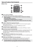
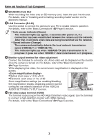
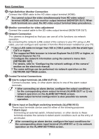
Name and Function of Each Component SD (SDHC) Card Slot When recording live video onto an SD memory card, insert the card into the slot. For details, refer to "Installing and formatting recording media" section on the electronic manual. LAN Connector (RJ-45) Use this socket to connect the camera to your PC to enable network operation. For details, refer to the "Basic Connections" ( Page 6) section. • Link access indicator (Green): This indicator lights up approx. 3 seconds after power on, if a connection has been established between the camera and the network. After that, it will blink when data are being transmitted via the network. • Speed indicator (Orange): The camera automatically detects the local network transmission speed (10BASE-T or 100BASE-TX). This indicator lights up when 100BASE-TX data transmission is in progress; it goes out when 10BASE-T data transmission is in progress. Monitor output terminal for video adjustment Connect this terminal to a monitor, etc. A live video will be displayed on the monitor once the camera is turned on. For details, refer to the "Basic Connections" ( Page 6) section. While displaying live video, the current zoom magnification is displayed on the screen. • Optical zoom area: ×1.0 to ×10.0 • Electronic zoom area: ×11 to ×160 Zoom magnification settings (ex. enabling/disabling the magnification display, displaying position) can be configured via network operation on the VIDEO & AUDIO SETTINGS (TV OUT) screen. x 10.0 ⤒ HD video output terminal (HDMI) The terminal outputs super-fine HD (High Definition) video signal. Use the terminal to connect a high-definition monitor with HDMI interface. For details, refer to the "Basic Connections" ( Page 6) section. 3
-
 1
1 -
 2
2 -
 3
3 -
 4
4 -
 5
5 -
 6
6 -
 7
7 -
 8
8 -
 9
9 -
 10
10 -
11
-
12
-
13
-
14
-
15
 |
 |