Sanyo VCC-HD4600 VCC-HD4600 Summary Manual - Page 7
Basic Connections
 |
UPC - 086483075704
View all Sanyo VCC-HD4600 manuals
Add to My Manuals
Save this manual to your list of manuals |
Page 7 highlights
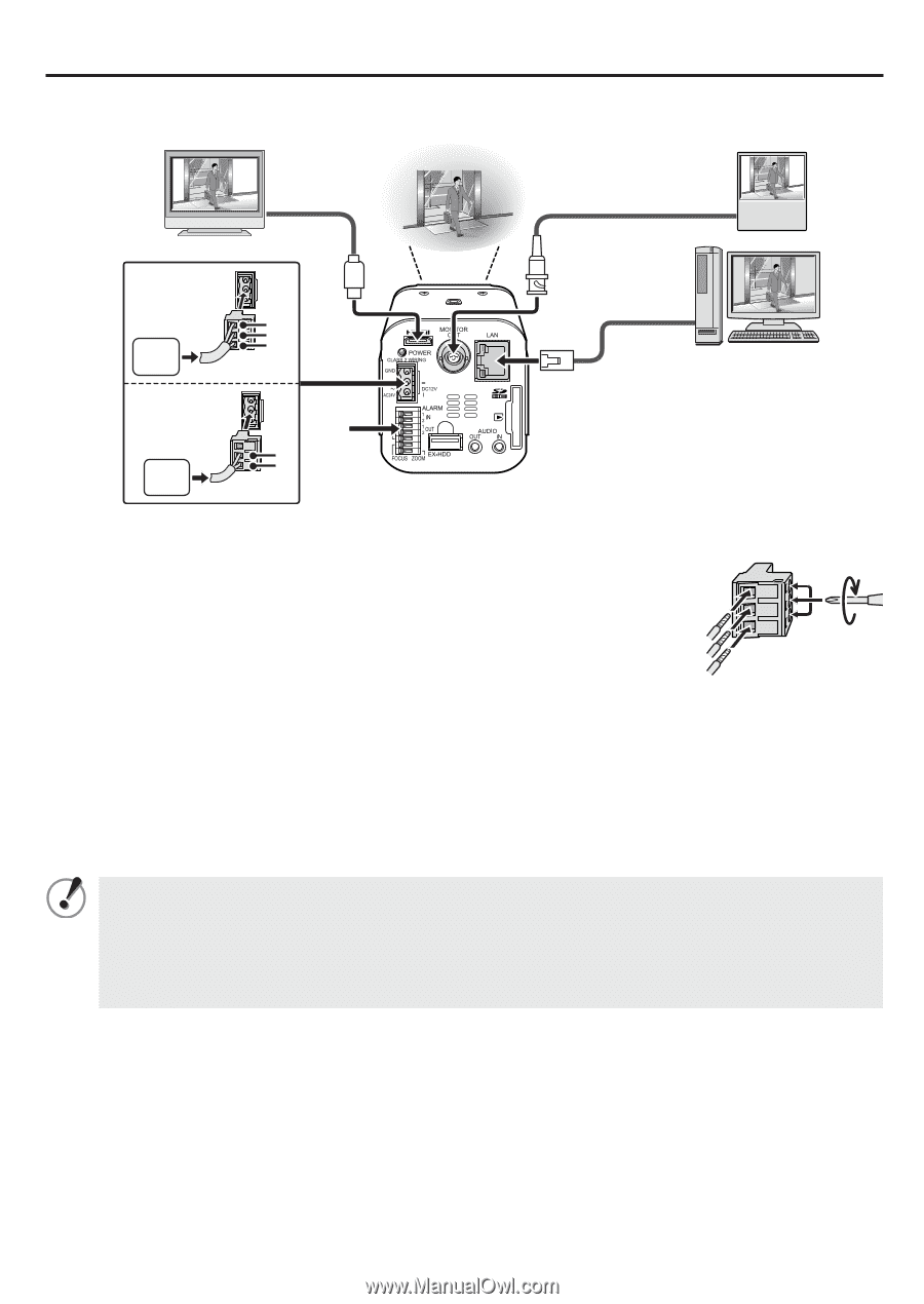
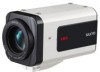
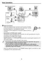
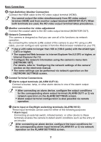
Basic Connections High-definition monitor ⦈ Target Monitor ⦉ 24 VAC 24 VAC 12 VDC 12 VDC GND ~ ~⦇ ⦋ + ⦊ PC ⦇ Power Connection Attach the supplied power connecter into the power terminal. Loosen the screws on the side face of the connecter, connect the power cables to it, and tighten the screws. Connection method depends on the power supply (24 VAC or 12 VDC). Connection to 24 VAC power supply: Although the power terminals have no polarity, the earth grounding wire must be connected to the COM (GND) terminal. Connection to 12 VDC power supply: Note the polarity (+/-) of the power terminals when connecting the camera to a 12 VDC power supply. Incorrect polarity may cause damage to the camera. • To prevent a fire hazard use any UL listed wire rated VW-1. Be sure to use an 18AWG or thicker wire power cable. • If you must use a long power cable, determine the cable type by ensuring that the voltage at the 24 VAC/12 VDC terminal is within the operating range of the camera. When the camera is powered on, the POWER indicator lights up and the live video is displayed on the connected monitor. 6
-
 1
1 -
 2
2 -
 3
3 -
 4
4 -
 5
5 -
 6
6 -
 7
7 -
 8
8 -
 9
9 -
 10
10 -
 11
11 -
 12
12 -
13
-
14
-
15
 |
 |