Sanyo VCC-HD4600 VCC-HD4600 Summary Manual - Page 8
Alarm input or Day/Night switching terminals ALARM IN1/2 - day night network camera
 |
UPC - 086483075704
View all Sanyo VCC-HD4600 manuals
Add to My Manuals
Save this manual to your list of manuals |
Page 8 highlights
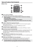
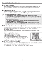
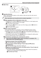
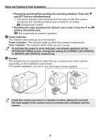
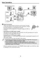
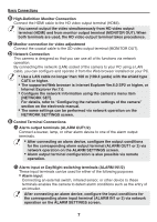
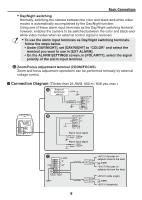
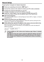
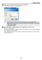
Basic Connections ⦈ High-Definition Monitor Connection Connect the HDMI cable to the HD video output terminal (HDMI). You cannot output the video simultaneously from HD video output terminal (HDMI) and from monitor output terminal (MONITOR OUT). When both terminals are used, the HD video output terminal takes precedence. ⦉ Monitor connection for video adjustment Connect the coaxial cable to the SD video output terminal (MONITOR OUT). ⦊ Network Connection This camera is designed so that you can use all of its functions via network operation. By connecting the network (LAN) socket of the camera to your PC using a LAN cable, you can configure and operate it from the Web browser installed on your PC. • Use a LAN cable no longer than 100 m (109.4 yards) with the shield type CAT5 or higher. • The supported Web browser is Internet Explorer Ver.6.0 SP2 or higher, or Internet Explorer Ver.7.0. • Configure the network information using the camera's menu item [NETWORK SET]. For details, refer to "Configuring the network settings of the camera" section on the electronic manual. • The same settings can be performed via network operation on the NETWORK SETTINGS screen. ⦋ Control Terminal Connections ⦇ Alarm output terminals (ALARM OUT1/2) Connect a buzzer, lamp, or other alarm device to one of the alarm output terminals. • After connecting an alarm device, configure the output conditions for the corresponding alarm output terminal (ALARM OUT1 or 2) via network operation on the ALARM SETTINGS screen. • Alarm output terminal configuration is also possible via remote operation. ⦈ Alarm input or Day/Night switching terminals (ALARM IN1/2) These input terminals can be used for either of the following purposes: • Alarm input Connecting an external switch, infrared sensor, or other device to these terminals enables the camera to detect alarm conditions such as the entry of an intruder. After connecting an alarm device, configure the input conditions for the corresponding alarm input terminal (ALARM IN1 or 2) via network operation on the ALARM SETTINGS screen. 7
-
 1
1 -
2
-
 3
3 -
 4
4 -
 5
5 -
 6
6 -
 7
7 -
 8
8 -
 9
9 -
 10
10 -
 11
11 -
 12
12 -
 13
13 -
14
-
15
 |
 |