Schwinn Tango Tandem Seven IPS Schwinn Owner's Manual - Page 29
Quill Stems, Threadless Stems
 |
View all Schwinn Tango Tandem Seven IPS manuals
Add to My Manuals
Save this manual to your list of manuals |
Page 29 highlights
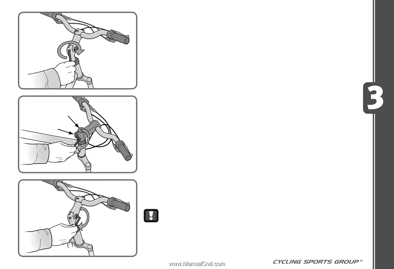
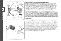
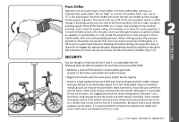
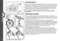
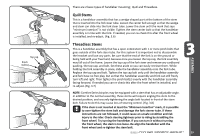
Top cap Pinch bolt(s) There are 2 basic types of handlebar mounting; Quill and Threadless. Quill Stems This is a handlebar assembly that has a wedge shaped part at the bottom of the stem that is inserted into the fork steer tube. Loosen the center bolt enough so that the wedge and stem can slide into the fork steer tube. Lower the stem until the mark that says "minimum insertion" is not visible. Tighten the stem center bolt so that the handlebar assembly is in line with the fork. If needed, you can re-check this after the front wheel is installed, and re-adjust. (Fig. 3.6) 3.6 Threadless Stems This is a handlebar assembly that has a open ended stem with 1 or more pinch bolts that goes outside of the fork steer tube. For this system it is important not to disassemble the headset and lose any parts. Be sure that the end of the fork is on the ground or being held with your free hand, because once you loosen the top cap, the fork assembly may fall out of the frame. Loosen the top cap of the fork steer and remove any cardboard packing, the top cap, and bolt. Set these aside so you can easily retrieve them. While holding the fork assembly in place, slide the handlebar assembly onto the fork tube. Replace the top cap and bolt. Tighten the top cap bolt only until the handlebar assembly and fork have no free play, but so that the handlebar assembly and fork can still freely turn left and right. Then tighten the pinch bolt(s) evenly with the handlebar assembly facing forward. If needed you can re-check this after the front wheel in installed, and 3.7 re-adjust. (Fig. 3.7) NOTE: Comfort Series bicycles may be equipped with a stem that has an adjustable angle. In addition to the normal assembly, these stems will require angling the stem to the desired position, and securely tightening the angle bolt located in front of the stem bolt. Failure to do this may cause loss of steering control. (Fig. 3.8) If the stem is not inserted at least the "Minimum Insertion" mark, it is possible to over-tighten the stem bolt and damage the fork steerer tube. If these instructions are not followed, it could cause an unsafe condition and risk injury to the rider. Check steering tightness prior to riding by straddling the front wheel. Try turning the handlebar. If you can turn it without turning the front wheel, the stem is too loose. Re-align the handlebar with the 3.8 front wheel and re-tighten the stem bolt. ©2010 29 ASSEMBLY
-
 1
1 -
2
-
3
-
4
-
5
-
6
-
7
-
8
-
9
-
10
-
11
-
12
-
13
-
14
-
15
-
16
-
17
-
18
-
19
-
20
-
21
-
22
-
23
-
 24
24 -
 25
25 -
 26
26 -
 27
27 -
 28
28 -
 29
29 -
 30
30 -
 31
31 -
 32
32 -
 33
33 -
 34
34 -
35
-
36
-
37
-
38
-
39
-
40
-
41
-
42
-
43
-
44
-
45
-
46
-
47
-
48
-
49
-
50
-
51
-
52
-
53
-
54
-
55
-
56
-
57
-
58
-
59
-
60
-
61
-
62
-
63
-
64
-
65
-
66
-
67
 |
 |