Sharp 20MR10 Service Manual
Sharp 20MR10 Manual
 |
View all Sharp 20MR10 manuals
Add to My Manuals
Save this manual to your list of manuals |
Sharp 20MR10 manual content summary:
- Sharp 20MR10 | Service Manual - Page 1
MANUAL S11O220MR10 COLOR TELEVISION Chassis No. SN-010 POWER VOL CH VIDEO IN AUDIO MENU MODEL 20MR10 ...4 INSTALLATION AND SER VICE INSTRUCTIONS 5 CHASSIS LAYOUT ...11 BLOCK prior notice. SHARP CORPORA TION This documenthas been publishedto be used for after sales service only. 1 The - Sharp 20MR10 | Service Manual - Page 2
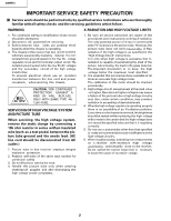
service personnel are aware of the procedures and instructions covering X-radiation. The only potential source of X-ray in current solid state TV an X-radiation problem. Every time a colorchassis is serviced,the brightness high voltage circuitry. 6. When troubles hooting and taking test measurements - Sharp 20MR10 | Service Manual - Page 3
20MR10 IMPORTANT SER VICE SAFETY PRECAUTION (Continued EARTH GR OUND SAFETY NOTICE Many electrical and mechanical parts in television recevers have special safety-related characteristics. These characteristics are often this service manual, may create shock, fire, X-radiation or other hazards. 3 - Sharp 20MR10 | Service Manual - Page 4
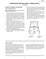
20MR10 LOCATION OF USER'S CONTROL Front Panel SENSOR AREA FOR REMOTE CONTROL POWER Press On. Press UP/DOWN (+) Increases sound. (-) Decreases sound. • In menu mode, changes or selects the TV adjustments. MUTE Press Mutes sound. Press again Restores sound. • CLOSED CAPTION appears when sound is - Sharp 20MR10 | Service Manual - Page 5
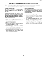
20MR10 INSTALLATION AND SER VICE INSTRUCTIONS Note: (1) When performing any adjustments to resistor controls and transformers use non-metallic screwdrivers or TV alignment tools. (2) Before performing adjustments, the TV signal. 3. Enter the service mode and select the service adjustment "S03" and - Sharp 20MR10 | Service Manual - Page 6
. Now, the TV set is switched on and enters the service mode. To exit the service mode, turn the television off by pressing the power button. 1. Service mode. Before putting unit into the service mode, check that (OSD disturbance can be erased by R/C display key) (Note: EEPROM - factory used only) 6 - Sharp 20MR10 | Service Manual - Page 7
BD FM LEVEL AFC GAIN G DRIVE FBT BLK SW V COMP OSD CONT SHARPNESS FLT SYS KILLER OP Y PRI CORING DC REST BS START BS GAIN ABL START R/B ANGLE H BLK R H BLK L RANGE 00-FF 00-FF 00 color killer Must be "30" Note: Refer to the SERVICE ADJUSTMENT for each corresponding values. Table - C 7 20MR10 - Sharp 20MR10 | Service Manual - Page 8
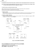
20MR10 Holding down both the Vol-up/Ch-down buttons on the TV set at service mode for more than 2 seconds will automatically write the T X Holding down both the Vol-up/Ch-down buttons on the TV set in the service mode for more than 2 seconds will automatically write the above initial values into - Sharp 20MR10 | Service Manual - Page 9
noise or beat appears. Note: You have to exit the service mode first to select another channel. V ideo Level (TV Det Video Level) Adjustment 1. Receive a good local channel. 2. Enter the service mode signal category and select the service adjustment "S02". 3. Set the data value to "02" first, then - Sharp 20MR10 | Service Manual - Page 10
20MR10 Vertical-Size, V-Linearity and V-S Correction Adjustments 1. Receive a good local channel. 2. Enter the service mode DEF category and select the . Vertical-Phase Adjustment 1. Receive a good local channel. 2. Enter the service mode DEF category and select the adjustment "D03". 3. Adjust "D03" - Sharp 20MR10 | Service Manual - Page 11
CHASSIS LAYOUT H 20MR10 G F E D C B A 1 2 3 4 5 6 11 - Sharp 20MR10 | Service Manual - Page 12
20MR10 BLOCK DIAGRAM H G F E D C B A 1 2 3 4 5 6 12 - Sharp 20MR10 | Service Manual - Page 13
20MR10 DESCRIPTION OF SCHEMATIC DIAGRAM NOTES: 1. The unit of resistance "ohm" is omitted. (K=k =1000 , M=M ) 2. All resistors are 1/10 watt, unless otherwise noted. 3. All capacitors are µF, unless - Sharp 20MR10 | Service Manual - Page 14
(22p) VCCCCY1HH470J(47p) VCCCCY1HH220J(22p) VCEA0A1CW106M(10 (16V)) VRS-CY1JF123J(12k) VRS-CY1JF000J(0) VRS-CY1JF332J(3.3k) VRS-CY1JF152J(1.5k) VRS-CY1JF152J(1.5k) VRS-CY1JF222J(2.2K) G F 20MR10 E D C B A 1 2 3 4 5 6 7 8 9 10 11 12 14 15 - Sharp 20MR10 | Service Manual - Page 15
20MR10 SCHEMATIC DIAGRAM: CRT Unit H G F E D C B A 1 2 3 4 5 6 16 - Sharp 20MR10 | Service Manual - Page 16
20MR10 PRINTED WIRING BOARD ASSEMBLIES H G F E D C B PWB-A: MAIN Unit (Wiring Side) A 1 2 3 4 5 6 17 - Sharp 20MR10 | Service Manual - Page 17
20MR10 H G F E D C B PWB-A: MAIN Unit (Chip Parts Side) A 1 2 3 4 5 6 18 - Sharp 20MR10 | Service Manual - Page 18
20MR10 H G F PWB-B: CRT Unit (Wiring Side) E D C B PWB-B: CRT Unit (Chip Parts Side) A 1 2 3 4 5 6 19 - Sharp 20MR10 | Service Manual - Page 19
20MR10 Ref. No. Part No. Description Code PARTS LIST PARTS REPLACEMENT Replacement parts which have these special safety characteristics identified in this manual this service manual SHARP Parts Distributor to order. For location of SHARP Parts Distributor, Please call TollFree; 1-800-BE-SHARP - Sharp 20MR10 | Service Manual - Page 20
20MR10 Ref. No. Part No. Description PWB-A: DUNTKA358WEX0 MAIN UNIT (Continued) or VSSTP7NB60F-1 Q702 VS2SC945AQ/-1 or VS2SC3198Y/-1 Q751 VS2SC945AQ/-1 Q752 VS2SC945AQ/-1 or VS2SC3198Y/-1 Q2201 VS2SC3928R/-1 or - Sharp 20MR10 | Service Manual - Page 21
20MR10 Ref. No. Part No. Description Code PWB-A: DUNTKA358WEX0 MAIN UNIT (Continued) C304 VCCCCY1HH470J J 47p 50V Ceramic AA (IC201:iX3354CEZZ) C304 VCCCCY1HH220J J 22p 50V Ceramic AA ( - Sharp 20MR10 | Service Manual - Page 22
20MR10 Ref. No. Part No. Description Code PWB-A: DUNTKA358WEX0 MAIN UNIT (Continued) R211 VRS-CY1JF104J J 100k 1/16W M-Ox. AA R212 VRS-CY1JF000J J 0 1/16W M-Ox. AA R215 - Sharp 20MR10 | Service Manual - Page 23
20MR10 Ref. No. Part No. Description PWB-A: DUNTKA358WEX0 MAIN UNIT (Continued) R2044 VRS-CY1JF683J R2045 VRS-CY1JF101J R2047 VRS-CY1JF221J R2048 VRS-CY1JF562J R2049 VRS-CY1JF333J - Sharp 20MR10 | Service Manual - Page 24
20MR10 Ref. No. Part No. X Infrared R/C Unit AQ TiNS-7371GJZZ X Operation Manual AG PACKING PARTS (NOT REPLACEMENT ITEM) SPAKC0210GJZZ - Front Cabinet - 1-2 GCOVA0003GJSA X Cover for R/C AG 1-3 HBDGB1001GJSB X Badge, "SHARP" AF 1-4 JBTN-0003GJSD X Button(Power, Vol-up/down, AH CH-up/down - Sharp 20MR10 | Service Manual - Page 25
Ref. No. Part No. Wrapping Paper PACKING OF THE SET Description Code Ref. No. Part No. Polyethylene Bag 20MR10 Description Code Operation Manual Infrared R/C Unit Batteries Buffer Material FRONT Packing Case MARK : Not replacement items. 26 REAR Use tape to fix the top side of packing - Sharp 20MR10 | Service Manual - Page 26
20MR10 Ref. No. Part No. Description Code Ref. No. Part No. Description Code COPYRIGHT © 2001 BY SHARP CORPORATION ALL RIGHTS RESERVED. No part of this publication may be reproduced, stored in a retrieval system, or transmitted in any form or by any means, electronic, mechanical, photocopying,
-
 1
1 -
 2
2 -
 3
3 -
 4
4 -
 5
5 -
 6
6 -
 7
7 -
8
-
9
-
10
-
11
-
12
-
13
-
14
-
15
-
16
-
17
-
18
-
19
-
20
-
21
-
22
-
23
-
24
-
25
-
26
 |
 |

1
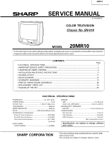
20MR10
COLOR TELEVISION
Chassis No. SN-010
In the interests of user-safety (Required by safety regulationsin some countries) the set should be restored to its
original
condition
and only parts
identical
to those specified
should
be used.
ELECTRICAL SPECIFICATIONS
.........................................................................................................
1
IMPORTANT SERVICE SAFETY PRECAUTION
.................................................................................
2
LOCATION OF USER'S CONTROL
.....................................................................................................
4
INSTALLATION AND SERVICE INSTRUCTIONS
................................................................................
5
CHASSIS LAYOUT
.............................................................................................................................
11
BLOCK DIAGRAM
..............................................................................................................................
12
SCHEMATIC DIAGRAMS
...................................................................................................................
13
PRINTED WIRING BOARD ASSEMBLIES
........................................................................................
20
REPLACEMENT PARTS LIST
............................................................................................................
23
PACKING OF THE SET
......................................................................................................................
29
Page
SHARP CORPORATION
This documenthas been publishedto be used for after
sales service only.
The
contents
are
subject
to
change
without
notice.
CONTENTS
SERVICE MANUAL
POWER INPUT
....................................................
AC 120 V, 60 Hz
POWER RATING
...................................................................
69 W
PICTURE SIZE
...........................................
1,194cm
2
(185sq inch)
CONVERGENCE
.............................................................
Magnetic
SWEEP DEFLECTION
....................................................
Magnetic
FOCUS
...............................................
Hi-Bi-Potential Electrostatic
INTERMEDIATE FREQUENCIES
Picture IF Carrier Frequency
.....................................
45.75 MHz
Sound IF Carrier Frequency
......................................
41.25 MHz
Color Sub-Carrier Frequency
....................................
42.17 MHz
(Nominal)
AUDIO POWER
OUTPUT RATING
.....................................................
1 W (RMS)
ELECTRICAL SPECIFICATIONS
SPEAKER
SIZE
......................................................................
8 cm (Round)
VOICE COIL IMPEDANCE
............................
32 ohm at 400 Hz
ANTENNA INPUT IMPEDANCE
VHF/UHF
.....................................................
75 ohm Unbalanced
TUNING RANGES
VHF-Channels
...............................................................
2 thru 13
UHF-Channels
............................................................
14 thru 69
CATV Channels
...........................................................
1 thru 125
(EIA, Channel Plan U.S.A.)
Specifications are subject to change without
prior notice.
MODEL
20MR10
S11O220MR10
POWER
VOL
CH
VIDEO
AUDIO
IN
MENU