Sharp 32F630 Service Manual
Sharp 32F630 - X-Flat Flat-Screen 32" TV Manual
 |
UPC - 074000357419
View all Sharp 32F630 manuals
Add to My Manuals
Save this manual to your list of manuals |
Sharp 32F630 manual content summary:
- Sharp 32F630 | Service Manual - Page 1
1st Edition 32F630 32F631 SERVICE MANUAL S13W527F630// COLOR TELEVISION Chassis No. GB-3U 32F630 32F630 32F631 MODELS 32F631 In the interests of user-safety (Required by safety regulations in some countries ) the set should be restored to its original condition and only parts identical to - Sharp 32F630 | Service Manual - Page 2
high voltage anode completely. X-RADIATION AND HIGH VOLTAGE LIMITS 1. Be sure all service personnel are aware of the procedures and instructions covering X-radiation. The only potential source of X-ray in current solid state TV receivers is the picture tube. However, the picture tube does not emit - Sharp 32F630 | Service Manual - Page 3
32F630 32F631 IMPORTANT SERVICE SAFETY PRECAUTION (Continued) BEFORE RETURNING THE RECEIVER (Fire & Shock Hazard) Before returning the receiver to the user, television necessarily increased by using replacement components replacement parts shown in this service manual, may rated for higher voltage - Sharp 32F630 | Service Manual - Page 4
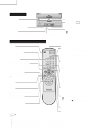
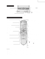
32F630 32F631 LOCATION OF USER'S CONTROL(32F630) Front Panel INPUT Press → Switches to external video INPUT 1 mode. Press twice → Switches to external video INPUT 2 mode. Press 3 times → Switches to external video INPUT 3 mode or COMPONENT mode. Press 4 times → Switches back to the original TV - Sharp 32F630 | Service Manual - Page 5
32F630 32F631 LOCATION OF USER'S CONTROL(32F631) Front Panel INPUT Press → Switches to external video INPUT 1 mode. Press twice → Switches to external video INPUT 2 mode. Press 3 times → Switches to external video INPUT 3 mode or COMPONENT mode. Press 4 times → Switches back to the original TV - Sharp 32F630 | Service Manual - Page 6
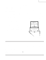
32F630 32F631 Note: INSTALLATION AND SERVICE INSTRUCTIONS (1) When performing any adjustments to resistor controls and transformers use non-metallic screwdrivers or TV alignment tools. (2) Before performing adjustments, the TV set must be on at least 15 minutes. CIRCUIT PROTECTION The receiver is - Sharp 32F630 | Service Manual - Page 7
32F630 32F631 For adjustments of this model, the bus data is converted to various analog signals by the D/A converter circuit. Note: There are still a few analog adjustments in this series such as focus and master screen voltage. Follow the steps below whenever the service adjustment is required. - Sharp 32F630 | Service Manual - Page 8
32F630 32F631 A. VCJ IC ADJUSTMENT SERVICE NUMBER ADJUSTMENT ITEM V01 PICTURE V02 TINT V03 COLOR V05 BRIGHT V06 R CUT-OFF V07 G CUT-OFF V08 B CUT-OFF V09 G/R DRIVE V10 B DRIVE V11 Y-MUTE/V-STOP V12 SHARP V13 DC RESTORATION V14 BLACK STRETCH V15 ABL START POINT V16 - Sharp 32F630 | Service Manual - Page 9
188 (BCh) 15 (0Fh) NOTES D. SOUND ADJUSTMENT SERVICE NUMBER ADJUSTMENT ITEM M01 INPUT LEVEL M02 MTS VCO M03 FILTER M04 WIDEBAND M05 SPECTRAL 15 (0Fh) 1 (01h) 15 (0Fh) 15 (0Fh) 17 (11h) 16 (10h) NOTES 32F630 32F631 FIXED VALUE (HEX) 32 00 00 00 0B 06 06 0B 32 02 02 FIXED VALUE (HEX - Sharp 32F630 | Service Manual - Page 10
32F630 32F631 Holding down both the VOL-up and CH-up buttons on the TV set at service mode for more than 2 seconds will PART the luminance as shown in figure "A" and "B" as below respectively. • COMPONENT INPUT 3. Get in service adjustment data "V42" and "V45" and set the luminance as shown in - Sharp 32F630 | Service Manual - Page 11
32F630 32F631 Holding down both the VOL-up and CH-up buttons on the TV set at service mode for more than 2 seconds will PART the luminance as shown in figure "A" and "B" as below respectively. • COMPONENT INPUT 3. Get in service adjustment data "V42" and "V45" and set the luminance as shown in - Sharp 32F630 | Service Manual - Page 12
data of "D24" same as "D05" data. (V-LIN) 32F630 32F631 Note: Aging for 10 min before adjustment. After the adjustment of V-center and V-size, readjustment for this V-line. Vertical Phase Adjustment (SCREEN FORMAT 4:3) 1. Enter the service mode and input data of "00h" on "D01". 2. Adjust "D18" data - Sharp 32F630 | Service Manual - Page 13
32F630 32F631 Ë MTS ADJUSTMENT MTS Level Adjustment 1. Set the sound volume above 1. Monoral signal: 400Hz, 100% modulation 2. Confirm "EX4" data is "5Ah". 3. Vary the "M01" bus data until the voltage to pin (39) of IC3001 to become the value as stated below. SETTING VOLTAGE ADJ spec : 490±10mVrms - Sharp 32F630 | Service Manual - Page 14
CHASSIS LAYOUT(32F630) 32F630 32F631 13 - Sharp 32F630 | Service Manual - Page 15
32F630 32F631 CHASSIS LAYOUT(32F631) 14 - Sharp 32F630 | Service Manual - Page 16
BLOCK DIAGRAM(32F630) 32F630 32F631 15 - Sharp 32F630 | Service Manual - Page 17
32F630 32F631 BLOCK DIAGRAM(32F631) 16 - Sharp 32F630 | Service Manual - Page 18
32F630 32F631 DESCRIPTION OF SCHEMATIC DIAGRAM NOTES: 1. The unit of resistance "ohm" is omitted. (K=kΩ=1000Ω, chart, waveforms are measured from point indicated to chassis ground.) å AND SHADED ( ) COMPONENTS = SAFETY RELATED PARTS. ç MARK= X-RAY RELATED PARTS. This circuit diagram is a - Sharp 32F630 | Service Manual - Page 19
32F630 32F631 SCHEMATIC DIAGRAM MAIN-1 UNIT (32F630) H 32F630 32F631 G F E D C B A 1 2 3 4 5 6 7 8 9 10 11 12 13 14 15 16 17 18 19 18 19 - Sharp 32F630 | Service Manual - Page 20
32F630 32F631 MAIN-1 UNIT (32F631) H G 32F630 32F631 - Sharp 32F630 | Service Manual - Page 21
32F630 32F631 MAIN-2 UNIT (32F630) H 32F630 32F631 G F E D C B A 1 2 3 4 5 6 7 8 9 10 11 12 13 14 15 16 17 18 19 22 23 - Sharp 32F630 | Service Manual - Page 22
32F630 32F631 MAIN-2 UNIT (32F631) H 32F630 32F631 G F E D C B A 1 2 3 4 5 6 7 8 9 10 11 12 13 14 15 16 17 18 19 24 25 - Sharp 32F630 | Service Manual - Page 23
32F630 32F631 3-LINE Y/C UNIT H 32F630 32F631 G F E D C B A 1 2 3 4 5 6 7 8 9 10 11 12 13 14 15 16 17 18 19 26 27 - Sharp 32F630 | Service Manual - Page 24
32F630 32F631 CONTROL UNIT(32F631 ONLY) H 32F630 32F631 G F E D C B A 1 2 3 4 5 6 7 8 9 10 11 12 13 14 15 16 17 18 19 28 29 - Sharp 32F630 | Service Manual - Page 25
32F630 32F631 DF MODULE UNIT H 32F630 32F631 G F E D C B A 1 2 3 4 5 6 7 8 9 10 11 12 13 14 15 16 17 18 19 30 31 - Sharp 32F630 | Service Manual - Page 26
32F630 32F631 CRT UNIT H G F E D C B A 1 2 3 4 5 6 32 - Sharp 32F630 | Service Manual - Page 27
AUDIO UNIT H 32F630 32F631 G F E D C B A 1 2 3 4 5 6 33 - Sharp 32F630 | Service Manual - Page 28
32F630 32F631 PRINTED WIRING BOARD ASSEMBLIES H G F E D C B A PWB-A: MAIN Unit (Components Side) 1 2 3 4 5 6 34 - Sharp 32F630 | Service Manual - Page 29
32F630 32F631 H G F E D C B A PWB-A: MAIN Unit (Chip Parts Side) 1 2 3 4 5 6 35 - Sharp 32F630 | Service Manual - Page 30
32F630 32F631 H G F E D PWB-B: CRT Unit (Wiring Side) C B A PWB-C: 3-LINE Y/C Unit (Wiring Side) 1 2 3 PWB-C: 3-LINE Y/C Unit (Chip Parts Side) 4 5 6 36 - Sharp 32F630 | Service Manual - Page 31
32F630 32F631 H G F E D C B PWB-H: DF MODULE Unit (Wiring Side) A 1 2 3 4 5 6 37 - Sharp 32F630 | Service Manual - Page 32
32F630 32F631 H G PWB-F: CONTROL Unit(32F631 ONLY) (Component Side) F E PWB-F: CONTROL Unit(32F631 ONLY) (Wiring Side) D C B A PWB-S: AUDIO Unit (Wiring Side) PWB-S: AUDIO Unit (Chip Parts Side) 1 2 3 4 5 6 38 - Sharp 32F630 | Service Manual - Page 33
32F630 32F631 Ref. No. Part No. 5 Description Code PARTS LIST PARTS REPLACEMENT Replacement parts which have these special safety characteristics identified in this manual ; electrical components having such features are identified by å and shaded areas in the Replacement Parts Lists and - Sharp 32F630 | Service Manual - Page 34
Ref. No. Part No. 5 Description Code Ref. No. Part No. 5 Description Code PWB-A: DUNTKB567WEW2(32F630) DUNTKB567WEX8(32F631) MAIN UNIT (Continued) D454 RH-EX0628GEZZ∗ X Zener Diode, 8.2V AB D455 VHD1SS119//-1∗ X 1SS119 AA D501 RH-DX0302CEZZ∗ X Diode AB D502 VHD1SS119//-1∗ X 1SS119 - Sharp 32F630 | Service Manual - Page 35
Ceramic AA C802 VCKYCY1HB222K∗ X 2200p 50V Ceramic AA C803 VCEA0A1HW224M+X 0.22 50V Electrolytic AA C804 VCKYCY1CF104Z∗ X 0.1 16V Ceramic AA 32F630 32F631 Ref. No. Part No. 5 Description Code C805 VCEA0A0JW108M+ X 1000 6.3V Electrolytic AB C806 VCKYCY1CF104Z∗ X 0.1 16V Ceramic AA C807 - Sharp 32F630 | Service Manual - Page 36
Ref. No. Part No. 5 Description Code PWB-A: DUNTKB567WEW2(32F630) DUNTKB567WEX8(32F631) MAIN UNIT (Continued) C3010 VCE9GA1HW475M+X 4.7 50V Electrolytic AB C3011 VCEA0A1HW475M+X 4.7 50V Electrolytic AA C3012 VCEA0A1HW475M+X 4.7 50V Electrolytic AA C3013 VCKYCY1HB272K∗ X 2700p 50V Ceramic - Sharp 32F630 | Service Manual - Page 37
Ref. No. Part No. 5 Description Code PWB-A: DUNTKB567WEW2(32F630) DUNTKB567WEX8(32F631) MAIN UNIT (Continued) å R604 VRS-KA3NG122J X 1.2k 7W Metal Oxide R605 VRD-RM2HD331J∗ X 330 1/2W Carbon AA R606 VRD-RM2HD331J∗ X 330 1/2W Carbon AA å R609 - Sharp 32F630 | Service Manual - Page 38
Ref. No. Part No. 5 Description Code PWB-A: DUNTKB567WEW2(32F630) DUNTKB567WEX8(32F631) MAIN UNIT (Continued) å R1420 VRN-RL3LB2R7J+ X QFS-B4023CEZZ X Fuse, 4A/125V AB J904 QJAKGA031WJZZ X Front In Jack(32F630) AC J921 QSOCD0430CEZZ X S-Video Terminal AC J1401 QTANJ1101SEZZ X In Out Jack - Sharp 32F630 | Service Manual - Page 39
AA Carbon AA Metal Oxide AA Carbon AA Metal Oxide AB Carbon AA Carbon AA Carbon AA Carbon AA Carbon AA Carbon AA 32F630 32F631 Ref. No. Part No. 5 Description Code R1520 VRD-RA2BE683J∗ X 68k 1/8W R1521 VRD-RA2BE122J∗ X 1.2k 1/8W R1525 VRD-RA2EE560J∗ X 56 1/4W R1526 VRD - Sharp 32F630 | Service Manual - Page 40
32F630 32F631 Ref. No. Part No. 5 Description Code PWB-C: DUNTKB573WEV0 3-LINE Y/C UNIT (Continued Switch, CH-DOWN S4006 QSW-KA003WJZZ+ X Switch, CH-UP MISCELLANEOUS PARTS J4001 QJAKGA031WJZZ X Input-2 Jack P4001 QPLGN0641CEZZ X Plug, 6Pin(EJ) P4004 QPLGN0541CEZZ X Plug, 5Pin(KA) RMC4001 - Sharp 32F630 | Service Manual - Page 41
X Connecting Cord AC QCNW-B240WJZZ X Connecting Cord(32F631) AE QCNW-B241WJZZ X Connecting Cord(32F631) AB SUPPLIED ACCESSORIES RRMCGA108WJSA X Infrared R-C Unit TiNS-A583WJZZ X Opearation Manual(32F630) AE TiNS-A660WJZZ X Opearation Manual(32F631) AE TGAN-0001GJZZ X Guarantee Card AB - Sharp 32F630 | Service Manual - Page 42
32F630 32F631 Ref. No. Part No. 5 Description CABINET PARTS 1A 1A-1 1A-2 1A-3 1A-4 1A-5 1A-6 1A-8 1A-7 32F630 CCABAA208WEH0 X Front Cabinet Cabinet 1B 1B-1 1B-2 1B-3 1B-4 1B-5 1B-6 1B-7 1B-8 32F631 CCABAA294WEH0 X Front Cabinet Ass'y Not Available - Front Cabinet HBDGB3141CESA X Badge - Sharp 32F630 | Service Manual - Page 43
5 Polyethylene Sheet PACKING OF THE SET 5 Polyethylene Bag 32F630 32F631 Operation Manual Infrared R/C Unit 5 Batteries 5Buffer Material FRONT 5 Packing Case 5 MARK : Not replacement items. REAR Use tape to fix the top side of packing case. Use 12 - Sharp 32F630 | Service Manual - Page 44
32F630 32F631 COPYRIGHT © 2003 BY SHARP CORPORATION ALL RIGHTS RESERVED. No part of this publication may be reproduced Design and Production Information Design : JAPAN Production : SEMEX MY. DS SHARP CORPORATION AV Systems Group Quality & Reliability Control Center Yaita, Tochigi 329-2193, Japan
-
 1
1 -
 2
2 -
 3
3 -
 4
4 -
 5
5 -
 6
6 -
 7
7 -
8
-
9
-
10
-
11
-
12
-
13
-
14
-
15
-
16
-
17
-
18
-
19
-
20
-
21
-
22
-
23
-
24
-
25
-
26
-
27
-
28
-
29
-
30
-
31
-
32
-
33
-
34
-
35
-
36
-
37
-
38
-
39
-
40
-
41
-
42
-
43
-
44
 |
 |

32F630
32F631
SHARP CORPORATION
This document has been published to be used for after
sales service only.
The contents are subject to change without notice.
In the interests of user-safety (Required by safety regulations in some countries ) the set should be restored to its
original condition and only parts identical to those specified should be used.
COLOR TELEVISION
Chassis No. GB-3U
Page
»
ELECTRICAL SPECIFICATIONS
.........................................................................................................
1
»
IMPORTANT SERVICE SAFETY PRECAUTION
.................................................................................
2
»
LOCATION OF USER'S CONTROL
.....................................................................................................
4
»
INSTALLATION AND SERVICE INSTRUCTIONS
................................................................................
6
»
SERVICE ADJUSTMENT
...................................................................................................................
10
»
CHASSIS LAYOUT
.............................................................................................................................
13
»
BLOCK DIAGRAM
..............................................................................................................................
15
»
DESCRIPTION OF SCHEMATIC DIAGRAMS & WAVEFORMS
........................................................
17
»
SCHEMATIC DIAGRAMS
...................................................................................................................
18
»
PRINTED WIRING BOARD ASSEMBLIES
........................................................................................
34
»
REPLACEMENT PARTS LIST
............................................................................................................
39
»
PACKING OF THE SET
......................................................................................................................
49
CONTENTS
SPEAKER
SIZE
........................................................
12 x 6 cm oval (2 pcs.)
VOICE COIL IMPEDANCE
...............................
8 ohm at 400 Hz
ANTENNA INPUT IMPEDANCE
VHF/UHF
.....................................................
75 ohm Unbalanced
TUNING RANGES
VHF-Channels
...............................................................
2 thru 13
UHF-Channels
............................................................
14 thru 69
CATV Channels
...........................................................
1 thru 125
(EIA, Channel Plan U.S.A.)
POWER INPUT
.....................................................
120V AC, 60 Hz
POWER RATING
..................................................................
160W
PICTURE SIZE
...........................................
3074 cm
2
(476sq inch)
CONVERGENCE
.............................................................
Magnetic
SWEEP DEFLECTION
....................................................
Magnetic
FOCUS
...............................................
Hi-Bi-Potential Electrostatic
INTERMEDIATE FREQUENCIES
Picture IF Carrier Frequency
.....................................
45.75 MHz
Sound IF Carrier Frequency
......................................
41.25 MHz
Color Sub-Carrier Frequency
....................................
42.17 MHz
(Nominal)
AUDIO POWER
OUTPUT RATING
..............
5.0W + 5.0W (at 10% distortion and
Dual CH Operate)
Specifications are subject to change without
prior notice.
ELECTRICAL SPECIFICATIONS
MODELS
SERVICE MANUAL
32F630
32F631
S13W527F630//
32F630
32F631
1st Edition