Sharp ER-A330 Installation Manual
Sharp ER-A330 Manual
 |
View all Sharp ER-A330 manuals
Add to My Manuals
Save this manual to your list of manuals |
Sharp ER-A330 manual content summary:
- Sharp ER-A330 | Installation Manual - Page 1
: 00ZERA310VIME ER-A310 ER-A330 ELECTRONIC CASH REGISTER MODEL ER-A310 MODEL ER-A330 SRV Key : LKGIM7113RCZZ PRINTER : ER-A310 : CR-510 : ER-A330 : UCR-812A (For "V" version) CONTENTS CHAPTER 1. GENERAL 1 CHAPTER 2. LIST OF OPTIONS 1 CHAPTER 3. REMOVING THE TOP CABINET (For ER-A310 & ER-A330 - Sharp ER-A330 | Installation Manual - Page 2
CASHIER KEY KIT 6 DRAWER FIXING KIT PARTS CODE LKGIM7113RCZZ LKGIM7126RCZZ GCÇVH7126BHZZ DKIT-8666BHZZ PRICE RANK AK AL BE BL DESCRIPTIONS OP key only Only for ER-A330 3. Supplies No. NAME 1 ROLL PAPER 2 INK ROLLER (ER-A310) 3 INK ROLLER (ER-A330) 4 INK FOR STAMP PARTS CODE DPAPR1006CSZZ - Sharp ER-A330 | Installation Manual - Page 3
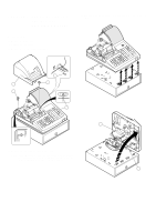
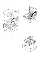
TOP CABINET (For ER-A310 & ER-A330) 1. ER-A310 1) Remove the printer cover . 2) Remove the two screws . 3) Remove the screw ! and grounding wire ". 5) Remove transformer cable # and drawer cable $ from the main PWB. 2 3 1 2 4 5 4) Separate the top cabinet and the drawer unit. Note: Transformer - Sharp ER-A330 | Installation Manual - Page 4
the three screws . 3) Remove the screw ! and grounding wire ". 5) Remove transformer cable # and drawer cable $ from the main PWB. 5 2 2 1 3 2 6 4 CHAPTER 4. REMOVING THE BOTTOM CABINET (Only for ER-A330) 4) Separate the top cabinet and the bottom cabinet. Note: Transformer cable # and the - Sharp ER-A330 | Installation Manual - Page 5
unit # from the top cabinet. CHAPTER 6. REMOVING THE MAIN PWB (For ER-A310 & ER-A330) 1. ER-A310/A330 1) Remove the top cabinet. 2) Remove the printer unit. 3) Remove the Remove the screw # and grounding wire $. 5) Remove the free screws % and main PWB &. 7 1 7 2 3 8 5 4 6 – 4 – - Sharp ER-A330 | Installation Manual - Page 6
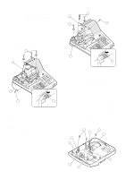
DRAWER: ER-04DW (For ER-A310 & ER-A330) CAUTION: The drawer unit should be securely fitted to the supporting platform to avoid instability when the drawer is open. 1. Outline The ER-A310/A330 allows connection of one remote drawer ER04DW. Note on the drawer connector The main PWB has no part - Sharp ER-A330 | Installation Manual - Page 7
3. Installation procedure for ER-A330 1) Remove the top cabinet. 2) Remove the main PWB. 3) Solder the drawer connector CN16, the resistor (1kΩ) R89, and the transistor (2SC3784) Q20 to the main PWB. 4) Replace the main PWB. 5) Connect the drawer cable to the drawer connector on the main PWB. 6) Use - Sharp ER-A330 | Installation Manual - Page 8
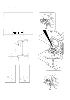
the bracket. Pan head screw Fixing bracket Rubber footing Cash drawer Fixing bracket Rubber footing Drawer bottom plate Pan head screw Fig. 1 3) Fastening SHIELD PLATE KIT: DKIT-8666BHZZ (Only for ER-A330) 1. Component list No. PARTS CODE DESCRIPTION Q'TY 1 LCHSM6705BHZZ SHIELD PLATE 1 - Sharp ER-A330 | Installation Manual - Page 9
the ERA330. 1. Component list No. PARTS CODE DESCRIPTION Q'ty 1 LKGIW7375BHZZ Clerk SW body 1 2 LKGIM7377BH01 Clerk key 1 2 3 LKGIM7377BH02 Clerk key 2 2 4 LKGIM7377BH03 Clerk key 3 2 5 LKGIM7377BH04 Clerk key 4 2 6 LKGIM7377BH05 Clerk key 5 2 7 LKGIM7377BH06 Clerk key 6 2 8 QCNW - Sharp ER-A330 | Installation Manual - Page 10
ER-22KT7 ER-12KT7 ER-12KT7, ER-22KT7 Note: There are black spacers and white spacers. Refer to the figure before for attaching them. ER-11KT7 ER-22KT7 • Attach the black spacer to the left lower side, and the white spacer to the right lower side. ER-11KT7 ER-12KT7 ER-11KT7 ! ER-11DK7, ER
-
 1
1 -
 2
2 -
 3
3 -
 4
4 -
 5
5 -
 6
6 -
 7
7 -
8
-
9
-
10
 |
 |
INSTALLATION MANUAL
CODE: 00ZERA310VIME
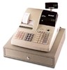
ELECTRONIC
CASH REGISTER
MODEL
ER-A310
MODEL
ER-A330
SRV Key : LKGIM7113RCZZ
PRINTER: ER-A310 : CR-510
:
ER-A330 : UCR-812A
(For "V" version)
CHAPTER
1.
GENERAL. . . . . . . . . . . . . . . . . . . . . . . . . . . . . . . . . . . . . . . . . . . . . .
1
CHAPTER
2.
LIST OF OPTIONS . . . . . . . . . . . . . . . . . . . . . . . . . . . . . . . . . . . . . . .
1
CHAPTER
3.
REMOVING THE TOP CABINET (For ER-A310 & ER-A330). . . . . .
2
CHAPTER
4.
REMOVING THE BOTTOM CABINET (Only for ER-A330). . . . . . . .
3
CHAPTER
5.
REMOVING THE PRINTER UNIT (For ER-A310 & ER-A330) . . . . .
4
CHAPTER
6.
REMOVING THE MAIN PWB (For ER-A310 & ER-A330). . . . . . . . .
4
CHAPTER
7.
REMOTE DRAWER: ER-04DW (For ER-A310 & ER-A330). . . . . . .
5
CHAPTER
8.
DRAWER FIXING KIT (DKIT–8633RCZZ). . . . . . . . . . . . . . . . . . . . .
6
CHAPTER
9.
SHIELD PLATE KIT: DKIT-8666BHZZ (Only for ER-A330). . . . . . . .
7
CHAPTER 10.
ONE HOLE CASHIER KEY KIT . . . . . . . . . . . . . . . . . . . . . . . . . . . . .
8
CHAPTER 11.
KEY TOP KIT: ER-11KT7/12KT7/22KT7/11DK7/51DK7
(For ER-A310 & ER-A330) . . . . . . . . . . . . . . . . . . . . . . . . . . . . . . . . .
8
CONTENTS
SHARP CORPORATION
This document has been published to be used
for after sales service only.
The contents are subject to change without notice.
Parts marked with " " is important for maintaining the safety of the set. Be sure to replace these parts with specified ones for
maintaining the safety and performance of the set.
ER-A310
ER-A330