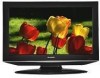
Sharp LC32DV24U Service Manual
Sharp LC32DV24U - 31.5" LCD TV Manual
 |
UPC - 074000371293
View all Sharp LC32DV24U manuals
Add to My Manuals
Save this manual to your list of manuals |
Sharp LC32DV24U manual content summary:
- Sharp LC32DV24U | Service Manual - Page 1
SERVICE MANUAL S68ONLC32DV24 COMBINATION LIQUID CRYSTAL TELEVISION AND DVD/CD PLAYER MODEL LC-32DV24U In the interests of user-safety (Required by safety regulations in some countries) the set should be restored to its original condition and only parts identical to those specified should be used. - Sharp LC32DV24U | Service Manual - Page 2
CAUTION THIS LCD COLOR TELEVISION EMPLOYS A LASER SYSTEM. TO ENSURE PROPER USE OF THIS PRODUCT, PLEASE READ THIS SERVICE MANUAL CAREFULLY AND RETAIN FOR FUTURE REFERENCE. SHOULD THE UNIT REQUIRE MAINTENANCE, CONTACT AN AUTHORIZED SERVICE LOCATION-SEE SERVICE PROCEDURE. USE OF CONTROLS, ADJUSTMENTS - Sharp LC32DV24U | Service Manual - Page 3
during lightning storms or when unused for long periods of time. 14) Refer all servicing to qualified service personnel. Servicing is required when the apparatus has been damaged in any way, such as power-supply cord or plug is S3126A damaged, liquid has been spilled or objects have fallen into - Sharp LC32DV24U | Service Manual - Page 4
810-20) GROUNDING CONDUCTORS (NEC SECTION 810-21) GROUND CLAMPS POWER SERVICE GROUNDING ELECTRODE SYSTEM (NEC ART 250, PART H) 20) When replacement parts are required, be sure the service technician uses replacement parts specified by the manufacturer or those that have the same characteristics as - Sharp LC32DV24U | Service Manual - Page 5
reminder is provided to call the cable TV system installer's attention to Article 820 . To prevent this, let the player stand in its new surroundings for about an hour LCD PANEL • Do not press hard or jolt the LCD panel. It may cause the LCD panel glass to break and injury may occur. • If the LCD - Sharp LC32DV24U | Service Manual - Page 6
the short circuit position after the connection of Pick Up PCB and DVD MT PCB connector. NOTE • Before your operation, please read "PREPARATION OF SERVICING". • Use the Lead Free solder. • Manual soldering conditions • Soldering temperature: 320 ± 20oC • Soldering time: Within 3 seconds • Soldering - Sharp LC32DV24U | Service Manual - Page 7
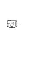
DISC REMOVAL METHOD AT NO POWER SUPPLY 1. Remove the Back Cabinet and Angle Deck. (Refer to item 1 of the DISASSEMBLY INSTRUCTIONS.) 2. Slide the Belt Loading toward the arrow direction by hand to release the lock. (Refer to Fig. 1) 3. Take out the Disc from the DVD Deck. Be careful not to scratch - Sharp LC32DV24U | Service Manual - Page 8
is 86°F~104°F(30°C~40°C) higher. Please use a soldering iron with temperature control and adjust it to 650°F ± 20°F (350°C ± 10°C). In case • All products with the printed circuit board with PbF printing must be serviced with lead free solder. When soldering or unsoldering, completely remove all of - Sharp LC32DV24U | Service Manual - Page 9
GENERAL SPECIFICATIONS G-1 TV System LCD Color System Speaker Sound Output G-2 DVD System Color System Disc LCD Size / Visual Size LCD Type Number of Pixels View Range Bright Dot Zero Bright Dot Ratio Position Size Impedance Max 10%(Typical) Left/Right Up/Down Disc Diameter Drive Search - Sharp LC32DV24U | Service Manual - Page 10
SPECIFICATIONS G-5 Power Power Source AC DC Power Consumption Stand by (at AC) Energy Star Per Year Protector Power Max Time On Timer Program Off Timer Program Game Timer Wake Up Timer Timer Back-up (at Power Off Mode) more than at AC at DC 120V, 60Hz -- 170W at 120V 60Hz -- - Sharp LC32DV24U | Service Manual - Page 11
G-10 Remote Control GENERAL SPECIFICATIONS Unit Glow in Dark Remocon Remocon Format Format Custom Code Power Source Total Keys Keys Voltage(D.C) UM size x pcs POWER DISPLAY SLEEP VIEW MODE INPUT SELECT 1 2 3 4 5 6 7 8 9 0 MUTE AUDIO VOL+ VOLCH+ CHLEFT/SLOWENTER RIGHT/SLOW+ UP DOWN SETUP/TV MENU - Sharp LC32DV24U | Service Manual - Page 12
G-11 Features (TV) GENERAL SPECIFICATIONS Auto Shut Off Auto Search Power On Memory Comb Filter Game Position Auto Setup(Language/CH Program) Picture Setting(TV) AV Mode(Picture Preference) Brightness , Contrast , Color Tint Sharpness Color Temperature DNR Cable Clear Picture Setting(PC - Sharp LC32DV24U | Service Manual - Page 13
Features (DVD) GENERAL SPECIFICATIONS HDMI Input Component Input Wall Mount Video CD Playback SVCD Playback MP3 Playback JPEG WMA Digital Out Down Mix Out Closed Caption Screen Saver TV Screen Audio DAC VGA (640×480) 720×480i (4:3) 720×480i (16:9) 720×480p (4:3) 720×480p (16:9) 720×576i (4:3) 720 - Sharp LC32DV24U | Service Manual - Page 14
GENERAL SPECIFICATIONS G-12 Accessories G-13 Interface Owner's Manual Language w/Guarantee Card Remote Control Unit Rod Antenna Poles Terminal Loop Antenna Terminal U/V Mixer DC Car Cord (Center+) Guarantee Card Warning Sheet Circuit Diagram Antenna Change Plug Service Facility List - Sharp LC32DV24U | Service Manual - Page 15
, Stand Approx. W x D x H (mm) Net (Approx.) Net w/o Handle, Stand (Approx.) Gross (Approx.) Master Carton Content Material Dimensions W / 5 Surfaces 32 321 Sets/40' container No No PC+ABS 94V0 NON-HALOGEN PS 94V0 NON-DECABROM -- No Yes Green procurement of SHARP Phase3(Phase3A) - Sharp LC32DV24U | Service Manual - Page 16
INSTRUCTIONS 1. REMOVAL OF MECHANICAL PARTS operation, please read "PREPARATION OF SERVICING". 2. Use the Lead Free solder. 3. Manual soldering conditions • Soldering temperature: CP2303). 13. Remove the 4 screws (6). 14. Remove the DVD MT PCB in the direction of arrow (E). Fig. 1-2 1-3: - Sharp LC32DV24U | Service Manual - Page 17
DISASSEMBLY INSTRUCTIONS 1-4: REMOCON PCB (Refer to Fig. 1-4) 1. Disconnect the following connector: (CP4201). 2. Remove Main. Angle Main (2) (2) Angle Main (1) (1) (1) LCD Block (1) Holder Panel-2 Holder Panel-1 Fig. 1-6 1-7: POWER PCB (Refer to Fig. 1-7) 1. Disconnect the following connectors - Sharp LC32DV24U | Service Manual - Page 18
DISASSEMBLY INSTRUCTIONS 1-8: ANGLE LCD TOP/ANGLE LCD BOTTOM AND ANGLE PCB-2 ASS'Y (Refer to Fig. 1-8) 1. Remove the 3 screws (1). 2. Remove the Angle Pcb-2 Ass'y and Holder Wire in the direction of arrow (A). 3. Remove the 2 screws (2). 4. Remove the Angle Lcd Bottom and Holder Wire in the - Sharp LC32DV24U | Service Manual - Page 19
INSTRUCTIONS 2. REMOVAL OF DVD DECK PARTS NOTE 1. Disassemble only the DVD DECK PARTS parts listed here. Minute adjustments are needed if the disassembly is done. If the repair is needed except listed parts, replace the DVD 3. Unlock the support (1). 4. Remove . 2-2-D. Manual soldering conditions - Sharp LC32DV24U | Service Manual - Page 20
Gear Motor Feed Motor DISASSEMBLY INSTRUCTIONS 8.0 ± 0.2mm [ 6 pin FFC ] 40 ± 1mm Fold Fold Safety surface for pressing of the insert. Fig. 2-2-C Switch PCB Ass'y ~ FEED MOTOR ~ WHITE (4) BROWN (3) • Install wire from (1) - Sharp LC32DV24U | Service Manual - Page 21
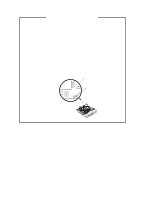
DISASSEMBLY INSTRUCTIONS 3. REMOVAL AND INSTALLATION OF FLAT PACKAGE IC REMOVAL 1. Put Masking Tape (cotton tape) around the Flat Package IC to protect other parts from any damage. (Refer to Fig. 3-1.) NOTE Masking is carried out on all the parts located within 10 mm distance from IC leads. 3. - Sharp LC32DV24U | Service Manual - Page 22
INSTRUCTIONS (Refer to Fig. 3-6.) Solder Soldering Iron IC Supply soldering from upper position to lower position Fig. 3-6 the soldering position and installation position of the parts around the IC. If some abnormality is found replace the IC in this case. Braided Shield Wire Fig. 3-7 B3-2 - Sharp LC32DV24U | Service Manual - Page 23
examine and adjust easily. To enter to the SERVICE MODE function, press and hold both buttons simultaneously on the main unit and on the remote control for more than a the standard time in the appropriate condition. (See below chart.) Set Condition TV mode Set Key VOL. DOWN (Minimum) Remocon Key - Sharp LC32DV24U | Service Manual - Page 24
Part No. APJG176140 Parts Name Up-Date Disc Remarks Up-Date of the Firmware RE-WRITE FOR DVD FIRMWARE 1. Turn on the power, and set the DVD mode. 2. Confirm that the "No Disc" will be appeared on the screen. 3. Press both VOL. DOWN button on the set and Channel button (5) on the remote control - Sharp LC32DV24U | Service Manual - Page 25
9. Turn on the Power. 10. Set the VOLUME to minimum. 11. Press both VOL. DOWN button on the set and Channel button (1) on the remote control for more than 2 seconds. 12. After the finishing of the initializing of shipping, the unit will turn off automatically. The unit will now have the correct DATA - Sharp LC32DV24U | Service Manual - Page 26
, HDMI and PC mode, press the INPUT button on the remote control. 6. To display the adjustment screen for DVD mode, press the TV/DVD button on the remote control. 7. Receive the DIGITAL broadcasting. 8. To display the adjustment screen for DTV mode, select the digital channel. 9. Press the VOL - Sharp LC32DV24U | Service Manual - Page 27
cent step No. becomes "129". 25. Check if the picture is normal. 26. Playback the DVD disc. (DVD Input) 27. Press the TV/DVD button on the remote control to set to the DVD mode. 28. Using the remote control, set the brightness and contrast to normal position. 29. Activate the adjustment mode display - Sharp LC32DV24U | Service Manual - Page 28
cent step No. becomes "96". 25. Check if the picture is normal. 26. Playback the DVD disc. (DVD Input) 27. Press the TV/DVD button on the remote control to set to the DVD mode. 28. Using the remote control, set the brightness and contrast to normal position. 29. Activate the adjustment mode display - Sharp LC32DV24U | Service Manual - Page 29
50 30 BAK LIGHT MAX 100 31 BAK LIGHT MIN 0 32 BRIGHT CENT 115 33 BRIGHT MAX 200 34 BRIGHT MIN 60 35 TINT 122 36 SHARP H1 MAX 511 37 SHARP H1 MIN 0 38 SHARP H2 MAX 511 39 SHARP H2 MIN 0 40 SHARP V1 MAX 511 41 SHARP V1 MIN 0 42 CONT CENTER * 43 CONT MAX * 44 CONT - Sharp LC32DV24U | Service Manual - Page 30
ELECTRICAL ADJUSTMENTS 3. ELECTRICAL ADJUSTMENT PARTS LOCATION GUIDE (WIRING CONNECTION) OPERATION 2 PCB CP2251 LCD PANEL OPERATION PCB CP2204 CP2203 DVD DECK CD2301 CD2001 CP2303 CP8502 CP2302 CP2301 DVD MT PCB CD8502 CP8501 CD8501 CD2804 CD2202 DIGITAL PCB CP4301 CP6202 TU5801 J4301 - Sharp LC32DV24U | Service Manual - Page 31
(LCD SECTION) POWER DOES NOT TURN ON TROUBLESHOOTING GUIDE Is F401 broken? Yes No Is there voltage at pin No 1 of IC402 6V? Yes Is R412 broken? Yes No Is there voltage at No - Sharp LC32DV24U | Service Manual - Page 32
TROUBLESHOOTING GUIDE THE PICTURE APPEARS, BUT THE AUDIO DOES NOT APPEARS. (AT RF MODE) No Is CP302 connected? Yes Is there signal at Yes pins 1 and 4 of No Yes - Sharp LC32DV24U | Service Manual - Page 33
TROUBLESHOOTING GUIDE THE PICTURE DOES NOT APPEAR No Does backlight shine? Yes No Is CD2804 connected? Yes Is there voltage at No pins 1, 2, 3, 4 and 5 of CP2804 5V? Yes Is - Sharp LC32DV24U | Service Manual - Page 34
TROUBLESHOOTING GUIDE THE COLOR DOES NOT APPEAR Is setting of color No normal? Yes Is the color signal No received? Yes Is there color signal No at IC2801? Yes Change DIGITAL PCB. Adjust the color. Receive the color signal. Check IC2801 and peripheral circuit. E-4 - Sharp LC32DV24U | Service Manual - Page 35
SECTION) DOES NOT DISPLAY DVD PICTURE TROUBLESHOOTING GUIDE Does this display Yes logo picture? No Is there signal at Yes pins 149 and 151 of IC4001? No Does IC4001 gets Yes P.CON+3.3V and P.CON+1.8V? No Check P.CON+3. - Sharp LC32DV24U | Service Manual - Page 36
TROUBLESHOOTING GUIDE DISC DOES NOT EJECT Does OSD appear No on the screen? Yes Is remote key set No effectively? Yes Check pins 138 and 139 of IC4001 and peripheral circuit. Does this eject disc at No change DVD DECK? Yes Change DVD DECK. Is there signal at pins 4 No and 5 of - Sharp LC32DV24U | Service Manual - Page 37
TROUBLESHOOTING GUIDE DOES NOT PLAY DVD Does this display Yes "INCORRECT DISC"? No Does CD2001 connect Yes with CP2301 correctly? No Connect CD2001. Change DVD DECK. No Is the voltage between JG017 and JG018 less than 0.6V? Yes Does this display No reading mark? Yes No Does disc - Sharp LC32DV24U | Service Manual - Page 38
TROUBLESHOOTING GUIDE DOES NOT PLAY CD Does this display Yes "INCORRECT DISC"? No Does CD2001 connect Yes with CP2301 correctly? No Connect CD2001. Change DVD DECK. No Is the voltage between JG019 and JG018 less than 0.6V? Yes Does this display No reading mark? Yes No Does disc - Sharp LC32DV24U | Service Manual - Page 39
TROUBLESHOOTING GUIDE NO SOUND DVD/CD ANALOG AUDIO Is there signal at pins No 113, 114, 115 and 116 of IC4001? Yes Is there signal at pins 1 No and 7 of IC8501? Yes No Does CD8501 connected? Yes Change DIGITAL PCB. NO SOUND DVD/CD DIGITAL AUDIO Change IC4001. Check pins 1 and 7 of IC8501 - Sharp LC32DV24U | Service Manual - Page 40
~D15, MEMCS0, RD, WR C,D APWM_L+/-, APWM_R+/- AUDIO AMP IC8501 NJM4565M(TE1) A LCD BLOCK DUPRD1 DUPTD1 TIN_SW SPDIF DAC_VIDEO_C/D DAC_VIDEO_A RESET SYS_MUTE TX RX START_SW SPDIF-134 C_VIDEO Y_VIDEO DVD RESET ZERO DVD_AUDIO_L DVD_AUDIO_R DVD_A_OUT_L DVD_A_OUT_R FLASH 16M SD_A0~A11 64M SDRAM - Sharp LC32DV24U | Service Manual - Page 41
FEED BACK IC410 PS2561AL1-1-V(W) 41 32 Q409 Q416 SW Q417 REGULATOR SW IC404 KIA431A-AT 13 Vcc SW 41 32 SW POWER SW TRANSFORMER IC406 T401 PS2561AL1-1-V(W) BACK IC408 SW PS2561AL1-1-V(W) 41 32 31 CP401__1.TUNER+30V CP401__7.8. AT+5V CP401__2. POWER FAIL CP401__6.P.CON+5V CP401__3. - Sharp LC32DV24U | Service Manual - Page 42
AT+3.3V 5 GND 6 P.CON+5V 7 8 AT+5V 9 10 GND 11 12 LCD+B 13 LCD_H 14 P.CON+9V 15 16 GND 17 STBY_H 18 SW+12V 19 REMOCON_IN 20 LIGHT_CTL 21 KEY_A 22 LIGHT_POWER_H 23 KEY_B POWER(DIGITAL PCB) BLOCK DIAGRAM DIGITAL TUNER TU5801 ENG36E19KF SUB MICON IC6202 R5F21124FP EEPROM - Sharp LC32DV24U | Service Manual - Page 43
SPDIF AUDIO L/R SPEAKER L/R SP301, SP302 S0412F06 AMP L/R SOUND AMP IC IC302 AN17808B C SW IC6555 MM1501XNRE SW_ Y_IN SW_ C_IN LVDS DATA/CLK LCD PANEL V2301 V315B1-L06 SCALER IC IC2801 R8J66954BG PC R PC G PC B PC IN CP4303 IN 1B630020 AUDIO ADC IC IC6551 AK5358A AUDIO DATA SUB - Sharp LC32DV24U | Service Manual - Page 44
R8527 C8544 IC8501 R8533 C8531 R8529 R8531 C8533 C8525 R8510 C8514 C8539 C8538 C8516 SH8502 SH8503 B4008 NTSC PAL DMG097A 4 CP8501 REGULATOR DVD MT (BOTTOM SIDE) R2306 R2318 Q2301 Q2302 C2333 C2335 C4006 C2332 R2355 R2309 C2339 C2331 R2350 C2321 B2304 R2353 C2323 C2338 C2336 - Sharp LC32DV24U | Service Manual - Page 45
G-3 SH3001 CP3001 PRINTED CIRCUIT BOARDS DIGITAL (TOP SIDE) CP2803 C2807 C2800 W854 LVDS C2801 MICON CP2804 W849 B2800 SH3002 CP2801 CP6201 SH3003 R6215 R6214 R6219 R6205 C6205 C3013 R3014 C2965 C2959 R2850 R2846 C2876 C2866 C2867 C2975 C2882 Q3003 Q3004 C3014 C3011 C3017 R3019 - Sharp LC32DV24U | Service Manual - Page 46
G-5 D3610 IC3601 C3604 R3609 R3613 R3615 PRINTED CIRCUIT BOARDS DIGITAL (BOTTOM SIDE) R4347 R4346 R4343 R4303 R4304 R4305 R3401 C3418 R3404 R3403 R3402 R3432 Q3408 R3431 Q3403 R3407 R3408 C3419 R3417 R3418 R3435 R3434 R3416 R3420 Q3401 Q3412 R3433 R3436 R2807 R2809 R2802 C2808 - Sharp LC32DV24U | Service Manual - Page 47
G-7 CP403 CP2201 R2208 C2205_1 PRINTED CIRCUIT BOARDS POWER/OPERATION/OPERATION2/REMOCON (INSERTED PARTS) SOLDER SIDE SH403 C401 OS2201 SH404 CP406 C458_2 D402 CP404 FH402 F401 FH401 AS MARKED. - REPLACE RISK OF FIRE SH401 SW SOLDER SIDE DED020A M2602 M2601 SW2 CD2301 WH BR YE GR G-8 - Sharp LC32DV24U | Service Manual - Page 48
Q410 IC411 R505 Q416 R458 Q408 R460 R430 C436 C425 R480 R461 R483 R484 C447 C454 C452 R2255 C2251 PRINTED CIRCUIT BOARDS POWER/OPERATION/OPERATION2 (CHIP MOUNTED PARTS) SOLDER SIDE R546 R549 Q420 R493_1 R2213 D421 R420 R508 R466 R417 C408 R414 C411 C412 C418 C409 R411 C414 R471 - Sharp LC32DV24U | Service Manual - Page 49
G H MPEG/MICON/DSP/RF_AMP SCHEMATIC DIAGRAM (DVD MT PCB) 8 8 RF OPU_B OPU_A OPU_F APWM1+ GPIO(35) GPIO(34)/RAMCKE/SPDIFIN GPIO(33)/AIN/SPDIFIN GPIO(32)/SPDIFO GPIO(31)/ABCLK GPIO(30)/ALRCLK VDDP USBVDD USBDP/GPO(67) THE DC VOLTAGE EACH PART WAS MEASURED WITH THE DIGITAL TESTER DURING PLAYBACK. B C D E F - Sharp LC32DV24U | Service Manual - Page 50
26 27 28 29 30 31 32 33 34 35 36 37 38 39 40 41 42 43 44 45 46 47 48 C D E F G MEMORY SCHEMATIC DIAGRAM (DVD MT PCB) HA16 C4064 0.1 F TO CHANGE WITHOUT NOTICE B C D NOTE:THE DC VOLTAGE EACH PART WAS MEASURED WITH THE DIGITAL TESTER DURING PLAYBACK. E F 2 PCB130 DMG097 1 G H - Sharp LC32DV24U | Service Manual - Page 51
TOUT_SW C2323 0.1 B R2355 3.3K W813 JG017 DVD LD CTL Q2301 KTA1505S-Y-RTK/P 2.6 1.9 2.3 1.6 1.6 0 NC 44 43 42 41 40 39 38 37 36 35 34 33 32 31 30 29 28 27 26 25 24 23 R2336 390 P.CON+A5V_D P.CON+3.3V_D NOTICE E NOTE:THE DC VOLTAGE EACH PART WAS MEASURED WITH THE DIGITAL TESTER DURING - Sharp LC32DV24U | Service Manual - Page 52
/RX 13 GND 12 START_SW 11 [U]C_VIDEO 10 [V]Y_VIDEO 9 [Y]_VIDEO 8 DVD RESET 7 DVD_A_OUT_L 6 GND 5 DVD_A_OUT_R 4 ZERO 3 GND 2 SPDIF-134 PART WAS MEASURED WITH THE DIGITAL TESTER DURING PLAYBACK. D CAUTION:SINCE THESE PARTS MARKED BY ARE CRITICAL FOR SAFETY,USE ONES DESCRIBED IN PARTS - Sharp LC32DV24U | Service Manual - Page 53
ACCESSORY 3.4 3.4 3.4 3.4 3.4 3.4 3.4 3.4 3.4 3.4 3.4 3.4 0 3.4 3.4 25 26 27 28 29 30 31 32 33 34 35 36 37 38 39 40 41 42 43 44 45 46 47 48 R2806 10K R2805 10K C2806 0.1 AT EACH PART WAS MEASURED WITH THE DIGITAL TESTER WHEN THE COLOR BROADCAST WAS RECEIVED IN GOOD CONDITION AND PICTURE IS NORMAL - Sharp LC32DV24U | Service Manual - Page 54
AND SUBJECT TO CHANGE WITHOUT NOTICE NOTE:THE DC VOLTAGE AT EACH PART WAS MEASURED WITH THE DIGITAL TESTER WHEN THE COLOR BROADCAST WAS RECEIVED IN GOOD CONDITION AND PICTURE IS NORMAL. B C D E F C2845 0.1 B C2844 0.1 B C2843 0.1 B C2841 0.1 B C2842 1 B C2849 0.1 B C2851 0.1 B R2829 1K - Sharp LC32DV24U | Service Manual - Page 55
R3642 4.7K HP_RST1 FROM SCALER POWER VDD33 HDMI1_CLK_P HDMI1_CLK_N C3608 0.1 3.1 HDMI_D0P 3 B1+ C3610 8P CH 2.3 E1 HDMI_XIN 25 26 27 28 29 30 31 32 33 34 35 36 3.1 3.1 0 3.1 3.1 3.3 3.1 3.1 0 3.1 3.1 0 NC NC AT EACH PART WAS MEASURED WITH THE DIGITAL TESTER WHEN THE COLOR BROADCAST - Sharp LC32DV24U | Service Manual - Page 56
THE DC VOLTAGE AT EACH PART WAS MEASURED WITH THE DIGITAL TESTER WHEN THE COLOR BROADCAST WAS RECEIVED IN GOOD CONDITION AND PICTURE IS NORMAL. CAUTION: VGA-G VGA-B AV3/AV4_Y AV3/AV4_PB AV3/AV4_PR TWIRE_RXDC TWIRE_TXDC DVD-H ROUT_FI LOUT_FI 4 ASW2 ASW1 SPDIF FROM REGULATOR2 D3.3V AT - Sharp LC32DV24U | Service Manual - Page 57
VCC10LVDS 0 J17 VSS10LVDS LVDS POWER/REF PLL POWER LVDS_CH0 LVDS_CH1 LVDS0OUT0M E19 - 20 RXIN2+ 19 V2301 V315B1-L06 LCD PANEL 6 LCD_TXCLKOUTLCD_TXCLKOUT+ GND 18 RXCLK IN EACH PART WAS MEASURED WITH THE DIGITAL TESTER WHEN THE COLOR BROADCAST WAS RECEIVED IN GOOD CONDITION AND PICTURE IS - Sharp LC32DV24U | Service Manual - Page 58
17 0.5 3.2 9 10 11 12 13 14 15 16 SUR_SW VREF 3.3V_POWER_H AVSS IIC_OFF IVCC 32 31 30 29 28 27 26 25 KEY_B R6211 100 R6212 100 3.4 3.4 3.4 3.4 2.9 DC VOLTAGE AT EACH PART WAS MEASURED WITH THE DIGITAL TESTER WHEN THE COLOR BROADCAST WAS RECEIVED IN GOOD CONDITION AND PICTURE IS NORMAL. E - Sharp LC32DV24U | Service Manual - Page 59
A B C D E F SCALER POWER SCHEMATIC DIAGRAM 8 (DIGITAL PCB) 7 FROM REGULATOR2 D3.3V B2810 HCB1608KF-221T20 W813 C D NOTE:THE DC VOLTAGE AT EACH PART WAS MEASURED WITH THE DIGITAL TESTER WHEN THE COLOR BROADCAST WAS RECEIVED IN GOOD CONDITION AND PICTURE IS NORMAL. E F C2914 6.3V 330 - Sharp LC32DV24U | Service Manual - Page 60
F G SURROUND SCHEMATIC DIAGRAM (DIGITAL PCB) FROM SCALER VIDEO/AUDIO DVD-H D3401 MA111 FROM JACK3 ZERO_MUTE FROM FLASH A_MUTE FROM MICON AUDIO_MUTE DC VOLTAGE AT EACH PART WAS MEASURED WITH THE DIGITAL TESTER WHEN THE COLOR BROADCAST WAS RECEIVED IN GOOD CONDITION AND PICTURE IS NORMAL. D E - Sharp LC32DV24U | Service Manual - Page 61
B BTSC DEMODULATOR IC IC5801 AN5832SA-E1V 1 2 3 4 5 6 7 8 9 10 11 12 13 14 15 16 32 31 30 29 28 27 26 25 24 23 22 21 20 19 18 17 3.5 PILOT DET NC NC 3.5 PLL L+R REF AND PICTURE IS NORMAL. CAUTION:SINCE THESE PARTS MARKED BY ARE CRITICAL FOR SAFETY,USE ONES DESCRIBED IN PARTS LIST ONLY - Sharp LC32DV24U | Service Manual - Page 62
FROM/TO SCALER POWER AD_A3.3V FROM/ PART WAS MEASURED WITH THE DIGITAL TESTER WHEN THE COLOR BROADCAST WAS RECEIVED IN GOOD CONDITION AND PICTURE DVD-H I2C_CLK I2C_DATA TO AV SWITCH2 ASW0 DVD-H 4 TO SURROUND DVD-H FROM/TO MICON I2C_CLK I2C_DATA MCU_SCIRXD MCU_SCITXD 3 FROM/TO REGULATOR2 LCD - Sharp LC32DV24U | Service Manual - Page 63
SCHEMATIC DIAGRAM IS THE LATEST AT THE TIME NOTE:THE DC VOLTAGE AT EACH PART WAS MEASURED 1 OF PRINTING AND SUBJECT TO CHANGE WITHOUT NOTICE WITH THE CONDITION AND PICTURE IS NORMAL. A B C H-29 D E F G 7 FROM/TO SCALER VIDEO/AUDIO LRCK SDOUT BCLK MCLK ASW0 SW_Y_IN SW_C_IN DVD-H 6 FROM - Sharp LC32DV24U | Service Manual - Page 64
.3V D5.0V GND 7 FROM/TO SCALER VIDEO/AUDIO LCD-H AT+3.3V VDIM D3.3V GND TO TUNER TUNER+30V GND 4 1K SW Q3003 0 KRC103SRTK TO SCALER POWER D3.3V D1.8V D1.0V GND 3 SH3001 PART WAS MEASURED WITH THE DIGITAL TESTER WHEN THE COLOR BROADCAST WAS RECEIVED IN GOOD CONDITION AND PICTURE - Sharp LC32DV24U | Service Manual - Page 65
MTZJ27B D425 200V 390 EE 1N5406FL-6737 C403_1 POWER CONTROL IC IC401 MP3A5038 0.22 1W W5RH3.5X5X1.0 CONTINUED PROTECTION AGAINST FIRE HAZARD, REPLACE ONLY WITH THE SAME TYPE FUSE PART WAS MEASURED WITH THE DIGITAL TESTER WHEN THE COLOR BROADCAST WAS RECEIVED IN GOOD CONDITION AND PICTURE - Sharp LC32DV24U | Service Manual - Page 66
GND 10 NC Analog/Dimming 11 W810 ON/OFF 12 PWM/Dimming 13 NC N.C(open) 14 6 R486 1K 1/4W R487 4.7K 1/4W C458_2 50V 10 YXF 2A 125V W814 LCD+B REG BLOCK DC/ CONDITION AND PICTURE IS NORMAL. CAUTION:SINCE THESE PARTS MARKED BY ARE CRITICAL FOR SAFETY,USE ONES DESCRIBED IN PARTS LIST ONLY - Sharp LC32DV24U | Service Manual - Page 67
LCD-H P.CON+9V STBY-H SW+12V IR_REMO VDIM BLON 2 NOTE:THIS SCHEMATIC DIAGRAM IS THE LATEST AT THE TIME 1 OF PRINTING AND SUBJECT TO CHANGE WITHOUT NOTICE NOTE:THE DC VOLTAGE AT EACH PART WAS MEASURED WITH THE DIGITAL TESTER WHEN THE COLOR BROADCAST WAS RECEIVED IN GOOD CONDITION AND PICTURE - Sharp LC32DV24U | Service Manual - Page 68
A B C D E F G AV SWITCH SCHEMATIC DIAGRAM 8 (POWER PCB) 7 6 AV3_PB AV3_Y 5 4 3 W883 W884 W885 P.CON+9V C6509_1 AND SUBJECT TO CHANGE WITHOUT NOTICE NOTE:THE DC VOLTAGE AT EACH PART WAS MEASURED WITH THE DIGITAL TESTER WHEN THE COLOR BROADCAST WAS RECEIVED IN GOOD CONDITION AND - Sharp LC32DV24U | Service Manual - Page 69
W819 C D E F SOUND SCHEMATIC DIAGRAM (POWER PCB) G H 8 C307 1B SOUND CH2 OUT MUTE 6 7 8 0 NC 0.7 0 GND VCC STAND -BY CH1 OUT 9 10 11 12 0 19.0 3.3 0.7 PICTURE IS NORMAL. A B C H-41 CAUTION:SINCE THESE PARTS MARKED BY ARE CRITICAL FOR SAFETY,USE ONES DESCRIBED IN PARTS - Sharp LC32DV24U | Service Manual - Page 70
A B C D E F JACK SCHEMATIC DIAGRAM 8 (POWER PCB) PC/DVI AUDIO IN J4201 MSJ-2000B_AG(O87) 7 1 R3 NOTE:THIS SCHEMATIC DIAGRAM IS THE LATEST AT THE TIME NOTE:THE DC VOLTAGE AT EACH PART WAS MEASURED OF PRINTING AND SUBJECT TO CHANGE WITHOUT NOTICE WITH THE DIGITAL TESTER WHEN THE COLOR - Sharp LC32DV24U | Service Manual - Page 71
AV4_PB AV3/AV4_PR FROM/TO REGULATOR STBY-H IR_REMO 4 GND C4256 0.22 F FROM POWER AT+5V P_GND 3 2 1 A H-45 NOTE:THIS SCHEMATIC DIAGRAM IS THE THE DC VOLTAGE AT EACH PART WAS MEASURED WITH THE DIGITAL TESTER WHEN THE COLOR BROADCAST WAS RECEIVED IN GOOD CONDITION AND PICTURE IS NORMAL. C D - Sharp LC32DV24U | Service Manual - Page 72
KEY_1 1 GND R2217 10 R2201 330 SH POWER SW2201_3 R2213 EVQ21505R 10 C2203 0.01 B R2214 2 AT+5V 3 STANDBY LED 4 POWER ON LED 5 OS 26 CD2201 E8254002 3 KEY_B 2 GND 1 OS 32 CD2202_1 E8234001 PCB270 CEG358 SH VOL PART WAS MEASURED WITH THE DIGITAL TESTER WHEN THE COLOR BROADCAST WAS - Sharp LC32DV24U | Service Manual - Page 73
5 SPINDLE MOTOR(-) 6 SPINDLE MOTOR(+) PCB640 DED020 SW2 ESE22MH22 M M2602 BCZ3B05 M M2601 JCV9B12 CAUTION:SINCE THESE PARTS MARKED BY ARE CRITICAL FOR SAFETY,USE ONES DESCRIBED IN PARTS LIST ONLY ATTENTION:LES PIECES REPAREES PAR UN ETANT DANGEREUSES AN POINT DE VUE SECURITE N'UTILISER QUE - Sharp LC32DV24U | Service Manual - Page 74
11 Analog/Dimming 12 ON/OFF 13 PWM/Dimming 14 N.C(open) 2 BLACK WHITE 1 POWER PCB PCB240 PICTURE IS NORMAL. CAUTION:SINCE THESE PARTS MARKED BY ARE CRITICAL FOR SAFETY,USE ONES DESCRIBED IN PARTS 12V 2 VDD+5V/12V 1 DVD MT PCB PCB130 DMG097 CD2804 LCD PANEL V2301 DIGITAL PCB PCBDH0 CEG352 - Sharp LC32DV24U | Service Manual - Page 75
100mV 16 SOUND 1ms 200mV 17 10us 200mV 12 1ms 200mV 18 NOTE: The following waveforms were measured at the point of the corresponding balloon number in the schematic diagram. I-1 - Sharp LC32DV24U | Service Manual - Page 76
µs 500mV 53 10µs 100mV 59 200ns 1V 54 MEMORY 100µs 500mV 55 NOTE: The following waveforms were measured at the point of the corresponding balloon number in the schematic diagram. I-2 - Sharp LC32DV24U | Service Manual - Page 77
203 203 112 203 203 203 203 203 203 103A 103C 103A 103B 110 108 201 204 201 PCB240 (POWER PCB ASS'Y) 203 132 132 113 203 143 104C 104B 104C 104 PCB130 (DVD MT PCB ASS'Y) 213 213 216 PCB270 (OPERATION PCB ASS'Y) 216 105A 105 128 105B 137 101I 101E - Sharp LC32DV24U | Service Manual - Page 78
MECHANICAL EXPLODED VIEW (PACKING DIAGRAM) CD3805 HOLDER CORD TM101 POLYBAG INSTRUCTION(RED CAUTION) INSTRUCTION BOOK(E/F/S) REGISTRATION CARD INFORMATION SHEET(FCC) INFORMATION SHEET(CEA) PACKAGE TOP PACKAGE STAND-TOP PACKAGE STAND-BOTTOM SCREW LAMIFILM BAG GIFT BOX PACKAGE BOTTOM J1-3 SHEET - Sharp LC32DV24U | Service Manual - Page 79
MECHANICAL EXPLODED VIEW (PACKING DIAGRAM) PACKAGE STAND-TOP FILM BAG (791WHA0159) SCREW FILM BAG (791WHA0160) PACKAGE STAND-BOTTOM J1-4 - Sharp LC32DV24U | Service Manual - Page 80
adjustments are needed if this condition is disassembled further more. If the repair is needed, replace the DVD MECHA ASS'Y. 602 SW2 705 604 704 PCB640 (SW PCB ASS'Y) CD2301 CLASS PART NO. PART NAME GREASE Y315061000 G-555G MARK AA NOTE: Applying positions AA for the grease are displayed - Sharp LC32DV24U | Service Manual - Page 81
761WSAA106 761WSAA104 761WPA0473 761WPA0474 761WPAA176 761WPA0508 761WSAA125 PLATE POWER ANGLE LCD TOP SHIELD DIGITAL ANGLE PCB-1 ANGLE LCD BOTTOM HOLDER SPEAKER-L HOLDER SPEAKER-R COVER HINGE HOLDER DVD ANGLE DVD-1 761WSA0466 761WSA0472 761WSBA018 800WR00084 722000A661 723000D739 723527A133 - Sharp LC32DV24U | Service Manual - Page 82
DVD DECK REPLACEMENT PARTS LIST REF. NO. PART NO. DESCRIPTION ! 600 A50N01P650 DVD MECHA ASS'Y A50N01P650 601 92SBB0033A LOADER SUB ASS'Y 602 92AAA0017A FEED RACK ASS'Y 603 92P100088A GEAR,MOTOR 604 92P100117A GEAR,MIDDLE 605 92P200017A INSULATOR, F 606 - Sharp LC32DV24U | Service Manual - Page 83
REPLACEMENT PARTS LIST PART NO. DESCRIPTION REMOCON PCB ASS'Y *** PCB *** A50X02PDA0M REMOCON PCB ASS'Y CEG359A *** DIODES *** 0021E9Q010 LED LTL-1BEFJ-002A *** CONNECTORS *** 069S250639 CONNECTOR PCB SIDE A2001WR2-5P *** OTHERS *** 077A038005 REMOTE CONTROLLER VO - Sharp LC32DV24U | Service Manual - Page 84
B4313 B4314 B4315 B5802 B5804 B5808 B5809 B6551 B6552 B6553 B6556 L3001 L3002 L3003 L3004 L3005 ELECTRICAL REPLACEMENT PARTS LIST TCAA3875SY TCAA3875SY TPAAA05001 TCAA3875SY TCAA3875SY TCAA3875SY T27T030190 T27T030190 T27T030190 TCAA3875SY TCAA3875SY TPAAA05001 TCAA3875SY TCAA3875SY TCAA3875SY - Sharp LC32DV24U | Service Manual - Page 85
SH3006 PCB130 D2303 D2304 D4002 D4003 D4005 ELECTRICAL REPLACEMENT PARTS LIST 0216S8331K 02D1000119 02D1000119 0216S8220K 0216SD220J 021AS9224J 0216S8220K YQ-12 YQ-12 YQ-12 YQ-12 YQ-12 DVD MT PCB ASS'Y *** PCB *** A50X02P130M DVD MT PCB ASS'Y DMG097A *** DIODES *** DGERMA1110 DGERMA1110 - Sharp LC32DV24U | Service Manual - Page 86
! R412 ! R416 ! R432 ! R445 ! R447 ! R473 ELECTRICAL REPLACEMENT PARTS LIST DGERMA1110 DIODE SILICON DGERMA1110 DIODE SILICON MA111-(TX) MA111-(TX) *** PIN YQ-12 YQ-12 YQ-12 YQ-12 POWER PCB ASS'Y *** PCB *** A50X02P240M POWER PCB ASS'Y CEG353A *** RESISTORS *** RC31X1125J R3K681S39J - Sharp LC32DV24U | Service Manual - Page 87
D421 D424 D425 D426 D427 D428 D432 D433 ! D435 ! D437 ! D440 ! D442 ! D443 ! D444 D445 D4207 D4209 D4210 D4211 D4212 ELECTRICAL REPLACEMENT PARTS LIST R3K78A102J R803R9102J R63881010J R,METAL OXIDE RC R,FUSE 1K OHM 2W 1K OHM 1/16W 1 OHM 1W *** CAPACITORS *** E7EYF4471M E7ESF3102M E7ESF3102M - Sharp LC32DV24U | Service Manual - Page 88
! T401 ! T402 ! J401 J4201 J4202 J4203 J4205 J4206 ELECTRICAL REPLACEMENT PARTS LIST DE7RB1202B DIODE ZENER D1VT001330 DIODE,SILICON UDZSNP12B TE-17 1SS133T-77 REGULATOR VO=3.3V IO=800MA FET 1CH STEP DOWN DC-DC CONTROL 4INPUT 1OUTPUT AUDIO SW AN17808B MP3A5038 MIP2F4 KIA431A-AT KIA431A-AT - Sharp LC32DV24U | Service Manual - Page 89
PCB270 SW2201 SW2202 SW2203 SW2204 SW2205 SW2206 CP2203 CP2204 PCB280 SW2251 SW2252 SW2253 SW2254 SW2255 CP2251 ELECTRICAL REPLACEMENT PARTS LIST *** CONNECTORS *** 06977NM020 069D01001A 069S280639 069D01001A 069D01001A 069S250639 06977NM020 CONNECTOR PCB SIDE CONNECTOR PCB SIDE CONNECTOR PCB - Sharp LC32DV24U | Service Manual - Page 90
ELECTRICAL REPLACEMENT PARTS LIST AND OTHERS *** CONNECTORS *** CD2804 06CHRU2211 CORD CONNECTOR CHRU2211 *** AC CORD *** SPEAKER S0412F06 S0412F06 TM101 076B0MR030 TRANSMITTER ETR0088-010171 ! V2301 09EV132026 LCD V315B1-L06 RESISTOR RC CARBON RESISTOR CAPACITORS CC CE CP CPP - Sharp LC32DV24U | Service Manual - Page 91
RESERVED. No part of this publication may be reproduced, stored in a retrieval system, or transmitted in any form or by any means, electronic, mechanical, photocopying, recording, or otherwise, without prior written permission of the publisher. SHARP ELECTRONICS CORPORATION Sharp Plaza, Mahwah
-
 1
1 -
 2
2 -
 3
3 -
 4
4 -
 5
5 -
 6
6 -
 7
7 -
8
-
9
-
10
-
11
-
12
-
13
-
14
-
15
-
16
-
17
-
18
-
19
-
20
-
21
-
22
-
23
-
24
-
25
-
26
-
27
-
28
-
29
-
30
-
31
-
32
-
33
-
34
-
35
-
36
-
37
-
38
-
39
-
40
-
41
-
42
-
43
-
44
-
45
-
46
-
47
-
48
-
49
-
50
-
51
-
52
-
53
-
54
-
55
-
56
-
57
-
58
-
59
-
60
-
61
-
62
-
63
-
64
-
65
-
66
-
67
-
68
-
69
-
70
-
71
-
72
-
73
-
74
-
75
-
76
-
77
-
78
-
79
-
80
-
81
-
82
-
83
-
84
-
85
-
86
-
87
-
88
-
89
-
90
-
91
 |
 |

In the interests of user-safety (Required by safety regulations in some countries) the set should be restored
to its original condition and only parts identical to those specified should be used.
MODEL
This document has been published to be used for
after sales service only.
The contents are subject to change without notice.
COMBINATION LIQUID CRYSTAL
TELEVISION AND DVD/CD PLAYER
CONTENTS
S68ONLC32DV24
CAUTION
.............................................................................................................................
IMPORTANT SAFEGUARDS
..............................................................................................
WHEN REPLACING DVD DECK
.........................................................................................
DISC REMOVAL METHOD AT NO POWER SUPPLY
........................................................
PARENTAL CONTROL-RATING
.........................................................................................
ABOUT LEAD FREE SOLDER (PbF)
..................................................................................
GENERAL SPECIFICATIONS
.............................................................................................
DISASSEMBLY INSTRUCTIONS
........................................................................................
SERVICE MODE LIST
.........................................................................................................
SERVICING FIXTURES AND TOOLS
.................................................................................
RE-WRITE FOR DVD FIRMWARE
......................................................................................
WHEN REPLACING EEPROM (MEMORY) IC
....................................................................
ELECTRICAL ADJUSTMENTS
...........................................................................................
TROUBLESHOOTING GUIDE
.............................................................................................
BLOCK DIAGRAM
...............................................................................................................
PRINTED CIRCUIT BOARDS
..............................................................................................
SCHEMATIC DIAGRAMS
....................................................................................................
WAVEFORMS
......................................................................................................................
MECHANICAL EXPLODED VIEWS
....................................................................................
DVD DECK EXPLODED VIEWS
.........................................................................................
REPLACEMENT PARTS LIST
.............................................................................................
Page
A1-1
A1-2~A1-4
A1-5
A1-6
A1-6
A1-7
A2-1~A2-7
B1-1~B3-2
C-1
C-2
C-2
C-3
D-1~D-6
E-1~E-9
F-1~F-8
G-1~G-10
H-1~H-52
I-1, I-2
J1-1~J1-4
J2-1
K1-1~K3-8
•
•
•
•
•
•
•
•
•
•
•
•
•
•
•
•
•
•
•
•
•
LC-32DV24U
SERVICE MANUAL
Parts marked with "
" are important for maintaining the safety of the set. Be sure to replace these parts with
specified ones for maintaining the safety and performance of the set.
SHARP CORPORATION